Turbomachine blade with a blade tip armor cladding

a turbomachine and blade technology, applied in the direction of propellers, propulsive elements, water-acting propulsive elements, etc., can solve the problem of thin overall coating of achieve the effect of significantly improving the durability of the blade tip armor cladding

Active Publication Date: 2011-05-17
MTU AERO ENGINES GMBH
View PDF38 Cites 19 Cited by
  • Summary
  • Abstract
  • Description
  • Claims
  • Application Information

AI Technical Summary

Benefits of technology

[0006]In view of the above, it is an object of the invention to provide a blade of a turbomachine, for example a gas turbine, wherein the blade tip is provided with an armor cladding and further features so that the blade is less subject to wear. The invention further aims to avoid or overcome the disadvantages of the prior art, and to achieve additional advantages, as apparent from the present specification. The attainment of these objects is, however, not a required limitation of the claimed invention.
[0009]The blade tip armor cladding is protected against wear by coating the blade tip armor cladding with at least one of the above described multilayer coating systems. The total layer thickness of the layers of a single multilayer coating system, or respectively of each one of plural multilayer coating systems, is less than 100 μm. Thus, the overall coating of the blade tip armor cladding is very thin. Furthermore, the achieved surface quality is very smooth, so that no negative aerodynamic influences arise. The seal effect and the durability of the blade tip armor cladding is thereby significantly improved relative to the prior art.

Problems solved by technology

Thus, the overall coating of the blade tip armor cladding is very thin.

Method used


Image

  • Turbomachine blade with a blade tip armor cladding
  • Turbomachine blade with a blade tip armor cladding

Examples


Embodiment Construction

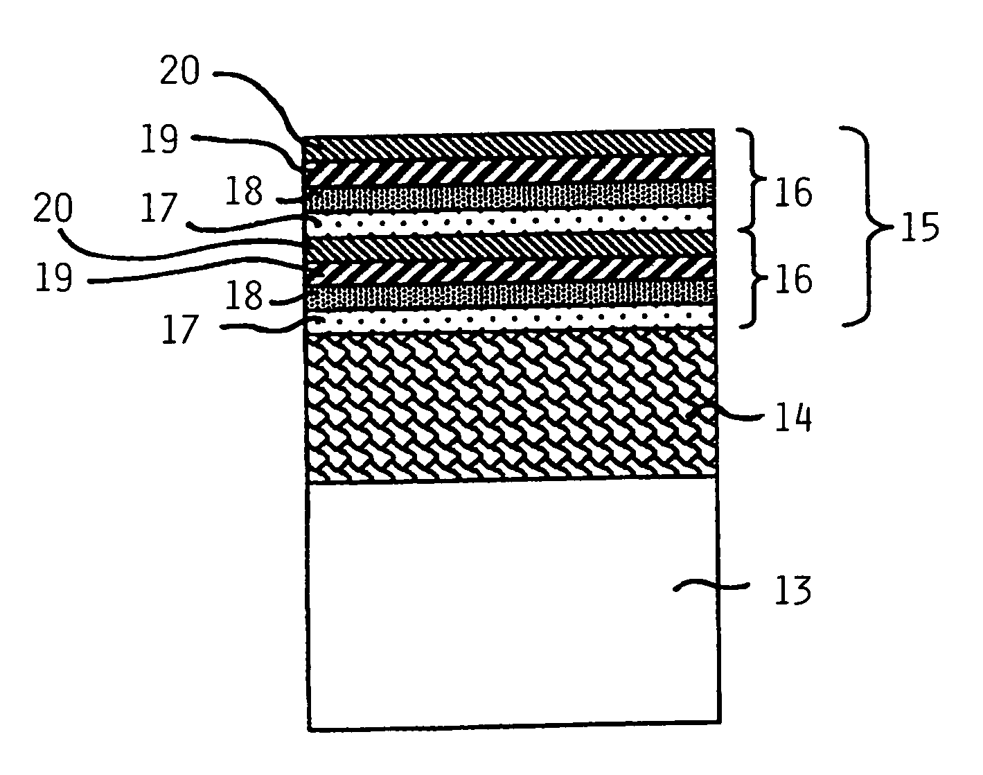
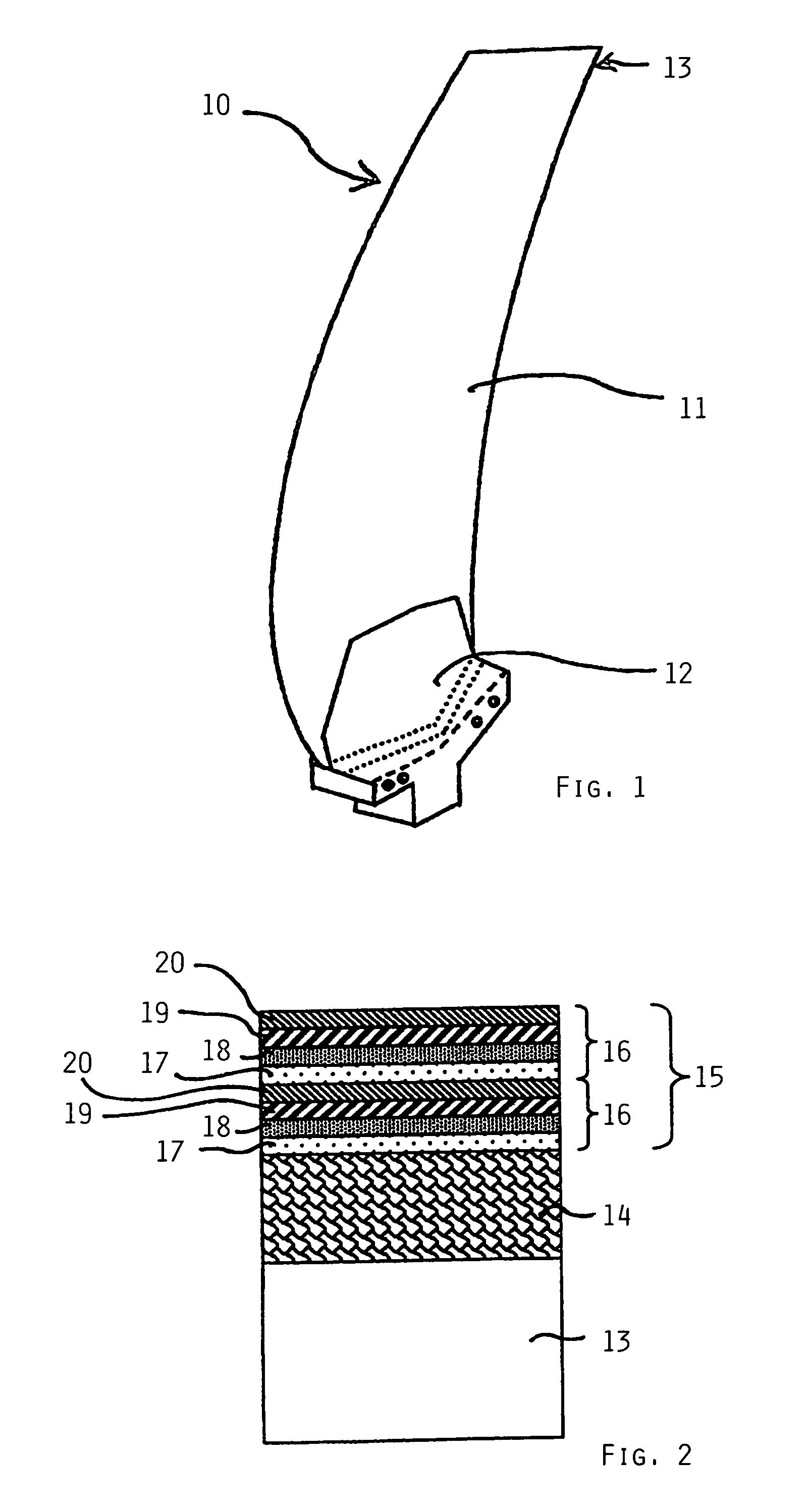
[0013]FIG. 1 schematically illustrates a rotor blade 10 of a gas turbine aircraft engine. The rotor blade 10 comprises a blade body including a blade vane 11, a blade root, pedestal or base 12 at a radially inner end of the blade vane 11, and a so-called blade tip 13 formed at a radially outer end of the blade vane 11. In order to protect the blade tip 13 against wear caused by so-called grazing contact thereof against a stationary housing or a seal component of the housing, the blade tip 13 is provided with a blade tip armor cladding 14. This armor cladding 14 can have any conventionally known or future developed composition, arrangement and provision on the blade tip 13. For example, according to the prior art, this armor cladding 14 can be formed of hard material particles or abrasive particles, and it may further include any suitable matrix if necessary.

[0014]Further according to the present invention, the blade tip armor cladding 14 is additionally covered or coated with a coat...


PUM

PropertyMeasurementUnit
thicknessaaaaaaaaaa
temperaturesaaaaaaaaaa
temperatureaaaaaaaaaa

Abstract

A blade of a turbomachine such as a gas turbine includes a blade vane with a blade tip and a blade base. A blade tip armor cladding is applied on the blade tip. A coating covers at least the armor cladding and includes at least one multilayer coating system, and preferably plural such coating systems stacked repetitively on one another. Each coating system includes at least two different layers stacked successively on one another, with one layer of a metal material closer to the blade tip and one layer of a ceramic material farther from the blade tip.

Description

PRIORITY CLAIM[0001]This application is based on and claims the priority under 35 U.S.C. §119 of German Patent Application 10 2005 030 266.1, filed on Jun. 29, 2005, the entire disclosure of which is incorporated herein by reference.FIELD OF THE INVENTION[0002]The invention relates to a blade of a turbomachine such as a gas turbine, whereby the blade has an armor cladding on the blade tip.BACKGROUND INFORMATION[0003]Turbomachines, such as gas turbines for example, typically comprise several stages of rotating rotor blades as well as stationary guide vanes. The rotor blades rotate together with a rotor. The rotor blades as well as the guide vanes are enclosed by a stationary housing of the gas turbine. In order to increase the output power and / or the efficiency of the gas turbine, it is important to optimize all components and sub-systems thereof, including the so-called seal systems. In a gas turbine aircraft engine, it is especially problematic to maintain a minimal gap between the...

Claims


Application Information

Patent Timeline
Patent Type & Authority Patents(United States)
IPC IPC(8): F01D5/28
CPCF01D5/28F01D5/284F01D5/286Y02T50/672Y02T50/673F05D2300/21Y10T428/12806Y10T428/12875Y10T428/12549Y10T428/12576Y10T428/12847Y10T428/12458F05D2300/611Y02T50/60
Inventor EICHMANN, WOLFGANGMANIER, KARL-HEINZUIHLEIN, THOMASUECKER, MARKUSHEUTLING, FALKO
Owner MTU AERO ENGINES GMBH
Why Eureka
Try Eureka