
Braze material and processes for making and using

a technology of brazing materials and brazing powders, which is applied in the direction of manufacturing tools, solvents, manufacturing tools, etc., can solve the problems of insufficient manufacturing or repair process of brazing, the tendency of some melting point depressants to form embrittling phases, and the limited temperature of brazing, so as to promote heating and melting of particles and enhance the mechanical properties of brazing

Active Publication Date: 2011-05-24
GENERAL ELECTRIC CO
View PDF25 Cites 13 Cited by
  • Summary
  • Abstract
  • Description
  • Claims
  • Application Information

AI Technical Summary

Benefits of technology

This approach enhances the mechanical properties of brazements, promotes broader use of brazing processes, and improves heating efficiency, particularly in gas turbine engine components, by ensuring localized melting and reduced segregation of melt-modifying constituents.

Problems solved by technology

For example, brazing temperatures are typically limited to avoid grain growth, incipient melting, recrystallization, and / or unfavorable phase formation.
A difficulty encountered when brazing certain alloys is the tendency for some melting point depressants to form embrittling phases, such as chromium borides that form when brazing chromium-containing superalloys.
As a result, brazing is not an appropriate manufacturing or repair process for some applications, particularly many components in the hot gas path of a gas turbine engine.
In any case, the amounts of melting point depressants contained in a braze alloy are intentionally limited and sometimes partitioned to minimize their detrimental effects.
However, segregation of the two powders can occur during the brazing process, with the lower-melting powder taking most of the working volume of the brazement and displacing the higher-melting powder.
If this occurs, an excess of melting point depressants will be present in the brazement, which in turn affects the mechanical properties of the brazement.
Drawbacks to this approach are lack of local heating of the braze alloy only, as an entire region of the component is inevitably heated, and significant heat loss from radiation in directions away from the intended brazement.

Method used


Image

  • Braze material and processes for making and using
  • Braze material and processes for making and using
  • Braze material and processes for making and using

Examples


Embodiment Construction

[0016]The invention will be described with reference to processing of components for a gas turbine engine, and particularly the fabrication, coating, buildup, and repair of such components with a braze material. However, the invention has application to a variety of components, materials, and processes other than those discussed, and such variations are within the scope of this invention.

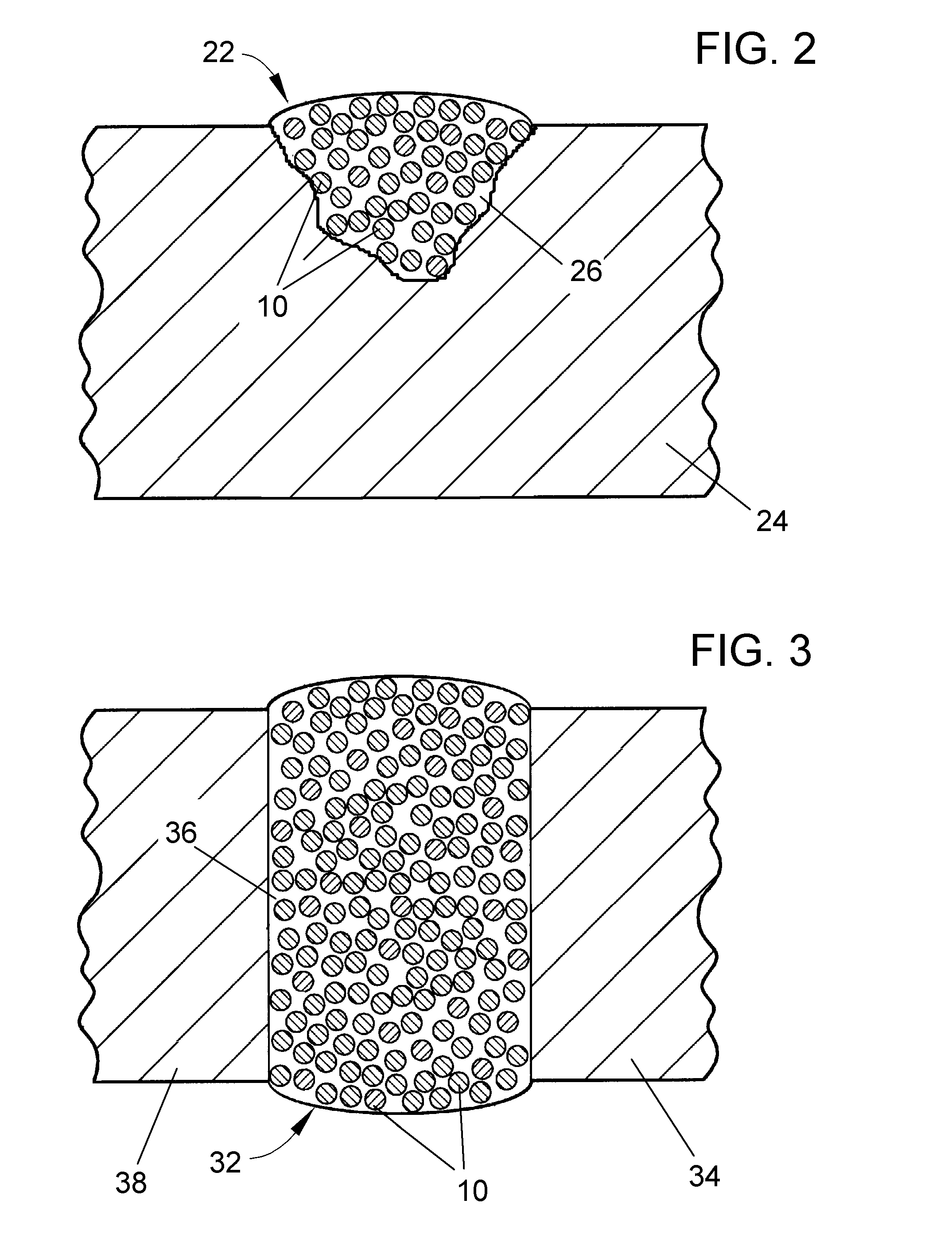
[0017]The present invention provides for the ability to enhance the processing and properties of brazements, such as braze joints, coatings, and repairs, by embedding very fine particulates of one or more melting point suppressants and / or microwave coupling enhancers into the outer surface of a particle whose composition can be a braze alloy tailored for the intended application. For example, for a gas turbine engine component formed of a superalloy, such as a nickel or cobalt-based superalloy, the braze alloy may have the very same superalloy composition as the component being brazed. In view of th...


PUM

PropertyMeasurementUnit
sizeaaaaaaaaaa
sizeaaaaaaaaaa
sizeaaaaaaaaaa

Abstract

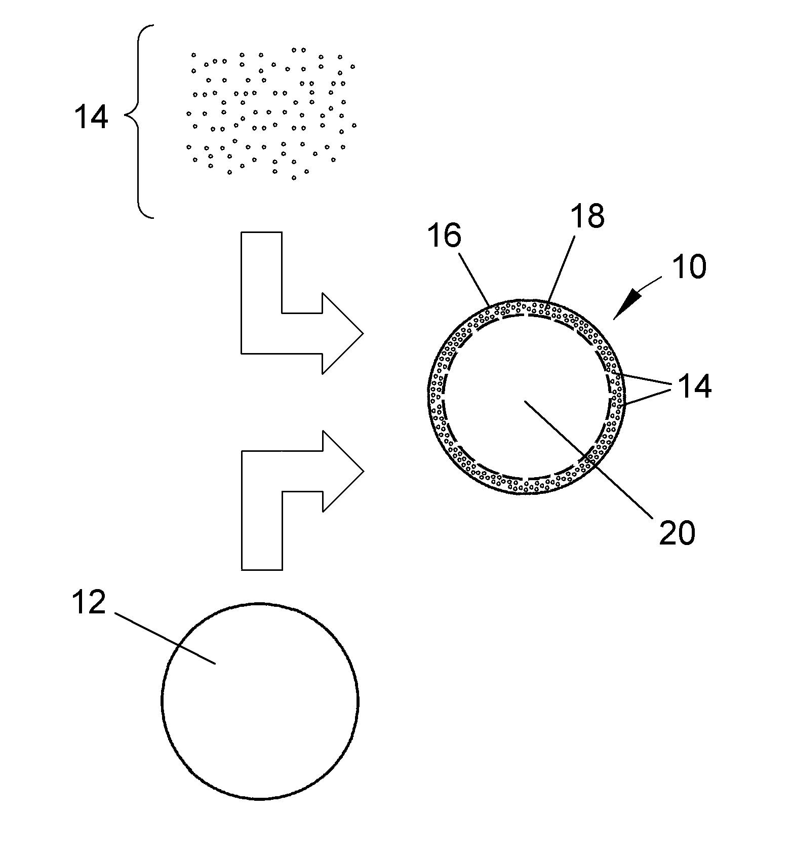
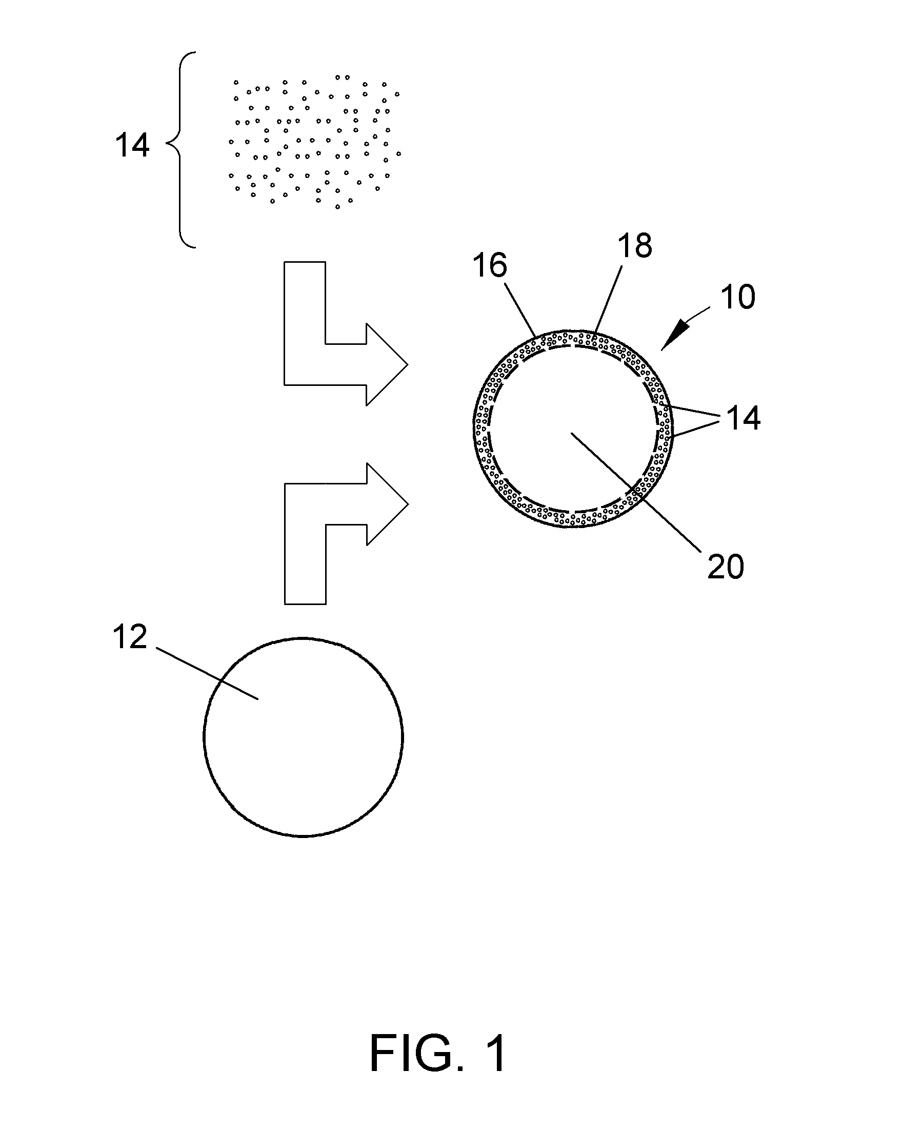
A braze material and processes for making and using the material, such as for use in the manufacturing, coating, repair, and build-up of superalloy components. The braze material is composed of particles with melt-modifying constituents that are limited to the surfaces of the particles, yet are capable of sufficiently promoting the heating of the particles by conventional means and microwave radiation to achieve at least partial melting of the particles. The melt-modifying constituents are in the form of particulates embedded in the outer surface region of each particle. The particulates are formed of melting point depressant(s) and / or microwave coupling enhancer(s), are much smaller than the particle in which they are embedded.

Description

BACKGROUND OF THE INVENTION[0001]This invention generally relates to braze materials and processes for making and using braze materials, such as for use in the manufacturing, coating, repair, and build-up of superalloy components. More particularly, this invention relates to braze material powders composed of particles with melt-modifying constituents on their surfaces, and to processes for producing and using such powders.[0002]Nickel, cobalt, and iron-base superalloys are widely used to form high temperature components of gas turbine engines. While some high-temperature superalloy components can be formed as a single casting, others are preferably or necessarily fabricated by other processes. As an example, brazing can be used to fabricate certain gas turbine components, such as high pressure turbine nozzle assemblies. Brazing is also used to repair cracks and other surface flaws and damage, build up surfaces to restore desired dimensions, and form protective coatings on gas turbi...

Claims


Application Information

Patent Timeline
Patent Type & Authority Patents(United States)
IPC IPC(8): B23K35/14
CPCB23K35/0244B23K35/24Y10T428/12146Y10T428/12028Y10T428/12181
Inventor CRETEGNY, LAURENT
Owner GENERAL ELECTRIC CO
Learn More