Self-orienting embedded in-situ flux system

a fluid flux and self-orienting technology, applied in the field of fluid flux measurement systems, can solve the problems of frequent calibration, unsuitable for small-scale turbulence measurement, unsuitable for remote deployment or deployment in uncontrolled conditions, etc., and achieve the effect of improving the quality of numerical weather prediction and fast respons

Active Publication Date: 2011-05-24
UNIV FOR ATMOSPHERIC RES
View PDF1 Cites 2 Cited by
  • Summary
  • Abstract
  • Description
  • Claims
  • Application Information

AI Technical Summary

Benefits of technology

[0010]Embodiments of the present invention provide for a sensor system that possesses the small-scale turbulence measuring capabilities of a heated element fluid flow sensor, and is able to make measurements over a wide range of mean wind direction. This may be accomplished by mounting a heated element fluid flow sensor on a movable member. The movable member may be operable to rotate the heated element fluid flow sensor to keep the wind mean direction within the angle of attack of the heated element fluid flow sensor. The movable member may be interconnected to the output of a motor. The movement of the heated element fluid flow sensor may be automated.
[0011]Embodiments of the present invention may include a repositionable protective member (e.g., a protective sleeve) that may be used to protect the heated element fluid flow sensor from potentially damaging conditions (e.g., strong winds, hail). The repositionable protective member may be operable to be positioned in a first position where it does not significantly affect measurement made by the heated element fluid flow sensor and a second position where it protects the heated element fluid flow sensor.
[0012]Furthermore, the present inventors have recognized that previous attempts to combine sonic anemometers and heated element fluid flow sensors have not been fully successful in overcoming the aforementioned issues with the individual sensors (e.g., the limited angle of attack). Embodiments of the present invention provide for a heated element fluid flow sensor interconnected to a movable member, where the heated element fluid flow sensor is disposed proximate to the measurement region of a sonic anemometer. In this regard, the movable member may allow for the heated element fluid flow sensor to be positioned such that the mean wind direction is within the angle of attack of the heated element fluid flow sensor. Thus the system benefits from the fast response and small-scale measurement capabilities of the heated element fluid flow sensor over a large range of mean wind directions due to the interconnection to the movable member. The sonic anemometer may also be used to calibrate the heated element fluid flow sensor in-situ, thereby eliminating the need for frequent laboratory calibration and enabling deployment in remote and / or difficult to access locations. The sonic anemometer may also be used to measure mean wind direction. This measurement may then be used to reposition the heated element fluid flow sensor.
[0013]Embodiments of the present invention disclosed herein may be beneficial to measure momentum flux and / or small-scale turbulent fluxes in the atmospheric boundary layer. This information may be used to aid in determining a variety of atmospheric characteristics. For example, the information may be used to improve the quality of numerical weather prediction, large-eddy simulation, global climate simulation, and worst-case air pollution and toxic substance calculations.

Problems solved by technology

However, generally sonic anemometers average their readings over a significant distance (e.g., about 10 cm) and have a sampling frequency that is too low, rendering them unsuitable for measuring small-scale turbulence.
However, generally, hot-film CTAs require frequent calibration due to drift, have a limited angle of attack (e.g., the angle in which they are able to make reliable measurements), and are relatively fragile, making them unsuitable for remote deployment or deployment in uncontrolled conditions.

Method used


Image

  • Self-orienting embedded in-situ flux system
  • Self-orienting embedded in-situ flux system
  • Self-orienting embedded in-situ flux system

Examples


Embodiment Construction

[0036]In the following description, an embodiment of the invention is set forth in detail in the context of an atmospheric measurement system. Indeed, the invention has a number of benefits and provides useful results in this regard. However, it will be appreciated that various aspects of the present invention are not limited to such atmospheric-based applications. Accordingly, the following description should be understood as exemplifying the invention and not by way of limitation.

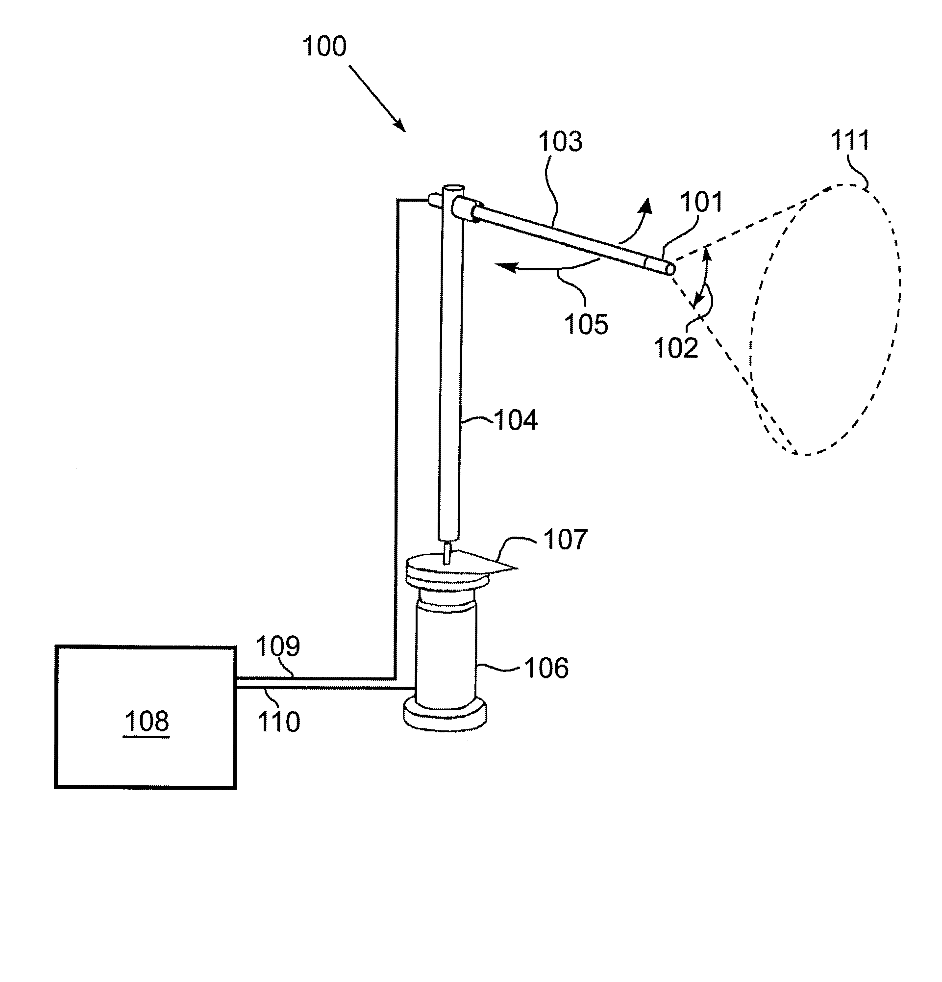
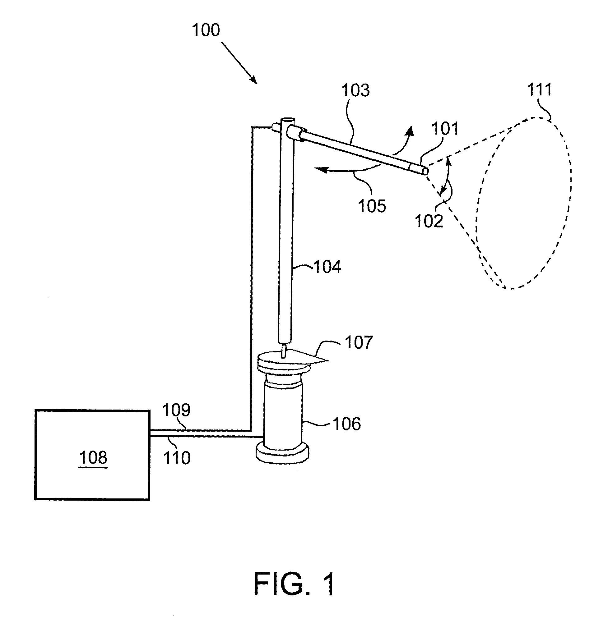
[0037]FIG. 1 is an illustration of a fluid flux measurement system 100 that includes a three-dimensional hot-film constant temperature anemometer (3D hot-film CTA) 101 mounted to an output member 104 of a motor 106. The 3D hot-film CTA 101 may include a plurality of fine heated elements that are heated to a temperature above ambient. The fluid flowing past the heated elements has a cooling effect on the heated elements. The heated elements may be made of metal and the resistance of the metal may be depend...


PUM

PropertyMeasurementUnit
angle of attackaaaaaaaaaa
angleaaaaaaaaaa
diameteraaaaaaaaaa

Abstract

A fluid flux measurement system that includes a heated element fluid flow sensor that is capable of being repositioned relative to a mean fluid flux direction is disclosed. The repositioning may be performed by a motor interconnected to the heated element fluid flow sensor. The heated element fluid flow sensor may be positioned proximate to the measurement region of a sonic anemometer and may be operable to be repositioned relative to the sonic anemometer. The heated element fluid flow sensor may be a three-dimensional hot-film constant temperature anemometer. The fluid flux system may be operable to measure small-scale turbulent fluxes in uncontrolled environments such as remotely located atmospheric monitoring stations. The heated element fluid flow sensor may be calibrated in-situ with data collected by the sonic anemometer.

Description

CROSS-REFERENCE TO RELATED APPLICATIONS[0001]This application claims the benefit of U.S. Provisional Application No. 60 / 939,261 filed May 21, 2007, which is incorporated herein by reference in its entirety.GOVERNMENT SUPPORT[0002]The present invention was made with Government support under Cooperative Agreement No. ATM-0301213 awarded by the National Science Foundation. The Government has certain rights in this invention.FIELD OF THE INVENTION[0003]This invention relates to fluid flux measurement systems in general, and in particular to methods and devices embodying a self-orienting in-situ fluid flux measurement system, and more particularly to methods and devices embodying a self-orienting and self-calibrating in-situ fluid flux measurement system operable to function in an uncontrolled environment, such as, the surface layer of the earth's atmosphere.BACKGROUND OF THE INVENTION[0004]There are many devices available for fluid flow measurement. Mechanical wind vanes and half-cup or...

Claims


Application Information

Patent Timeline
Patent Type & Authority Patents(United States)
IPC IPC(8): G01L1/00G01F1/00
CPCG01P5/12G01P13/02G01P5/245
Inventor POULOS, GREGORY S.SEMMER, STEVEN R.JACK, FOXJOHN, MILITZERMACLEAN, GORDON
Owner UNIV FOR ATMOSPHERIC RES
Why Eureka
Try Eureka