Rotary luminometer

a luminometer and rotary technology, applied in the field of luminometer subsystems, can solve the problems of variance in the accuracy of certain assays within automated immunoassay analyzers, and the inability to optimize individual assays, so as to reduce cross talk radiant light interference, optimize the time duration of the type of test being performed, and improve the accuracy of immunoassays.

Active Publication Date: 2011-05-31
SIEMENS HEALTHCARE DIAGNOSTICS INC
View PDF9 Cites 17 Cited by
  • Summary
  • Abstract
  • Description
  • Claims
  • Application Information

AI Technical Summary

Benefits of technology

[0011]It is still another object of the invention to provide a detection station for an automated immunoassay analyzer which allows for a variable and optimizable time period between a time when a chemical agent which reacts with bound analyte in a vessel is added to the vessel and a time when the amount of bound analyte is determined using the detector.
[0012]It is another object of the invention to provide an improved analyte detection station for an automated immunoassay analyzer which allows different tests performed in different vessels which are transported together on a transport section to be maintained for varying and different amounts of time in the transport section before being transferred to the detector for detection.
[0013]It is also an object of the invention to provide a detection station that reduces cross talk radiant light interference from other vessels in immunoassay analyzer.
[0014]According to the invention, an analyte detection station used in an automated immunoassay analyzer includes a transport device or mechanism for transporting a plurality of vessels (e.g., tubes, etc.) under investigation to a detector which preferably detects radiant energy (e.g., preferably chemiluminescence generated when a bound analyte cleaves a chemical substrate) or a color change (a color change detection would require a means for illuminating the vessel which is being read) that is indicative of the amount of bound analyte within the vessel (thereby providing a reading of the amount of analyte under investigation in the sample being tested). The detector is maintained in a housing separate from the transport device or mechanism, and a transfer device is used to individually transfer vessels from the transport device or mechanism to be presented to the detector. Preferably, the housing includes a rotary portion which moves the individual vessel from a point of transfer in the housing to a position in front of the detector where the vessel is completely shielded from radiant energy from the surrounding environment (e.g., stray light). In this way, the reading made by the detector accurately reflects only the radiant energy (or color change) in the vessel, and thereby permits highly accurate determination of the analyte of interest in the sample under investigation. The housing is also preferably configured to allow easy disposal of vessels after the detector has made a reading.
[0015]Furthermore, the analyte detection station of the present invention permits performing analyte detection in a randomized fashion, as opposed to a serial, one after the other, fashion. This allows for varying the time period between adding chemical reagents to the test vessel that interact with bound analyte to produce radiant energy or color change, and the time when the individual vessels are presented to the detector for analysis. In this way, the time duration for the type of test being performed can be optimized. This is accomplished by having the transport section separate from the detector section, whereby transfer from the transport section to the detector section occurs under the direction of a controller which effects the transfer at an interval that is preferably optimized for the test being performed, as well as in light of the other tests which are currently on the transport device.

Problems solved by technology

This does not allow optimization for the individual assay.
This may cause some variances in the accuracy of certain assays within the automated immunoassay analyzer.

Method used


Image

  • Rotary luminometer
  • Rotary luminometer
  • Rotary luminometer

Examples


Embodiment Construction

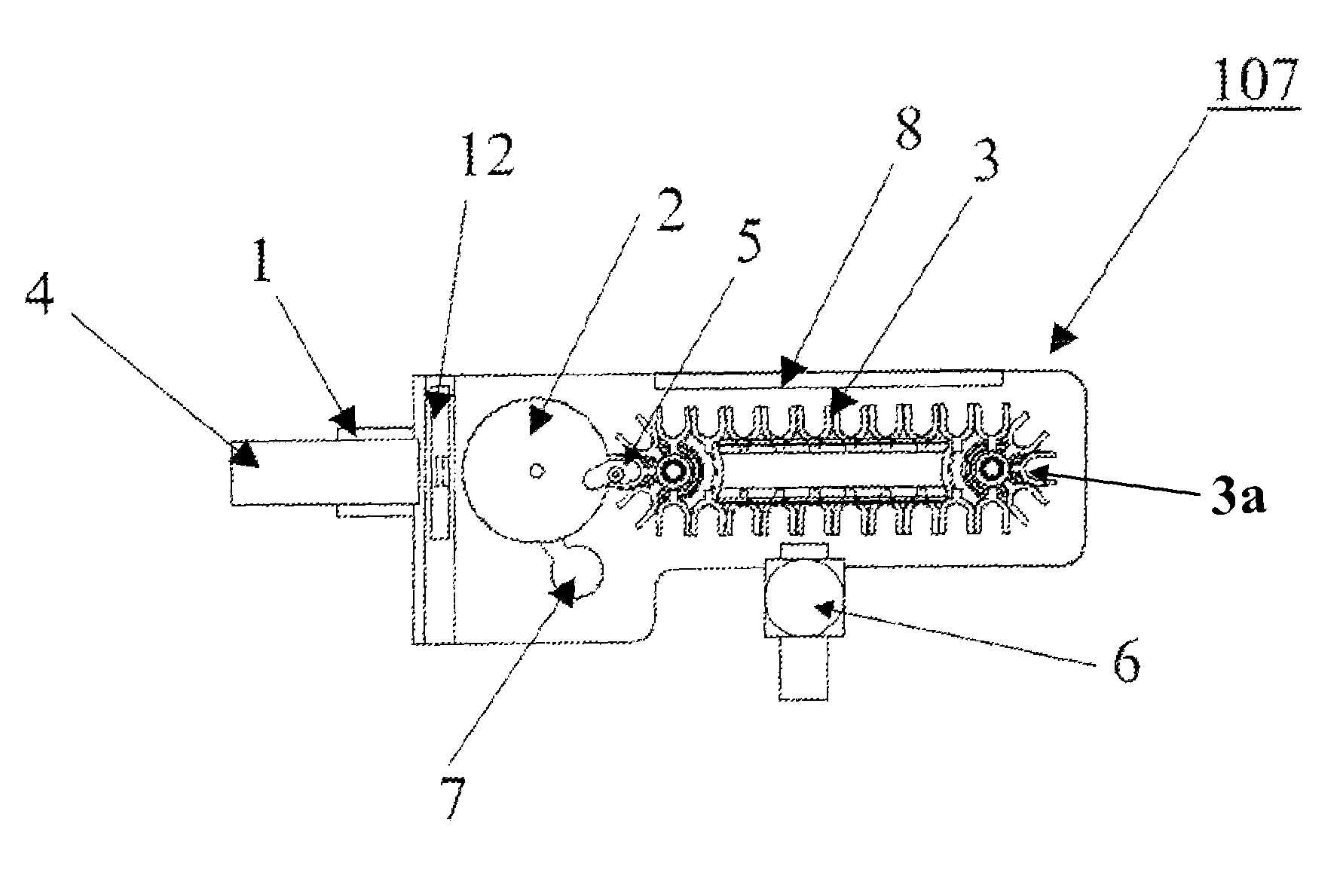
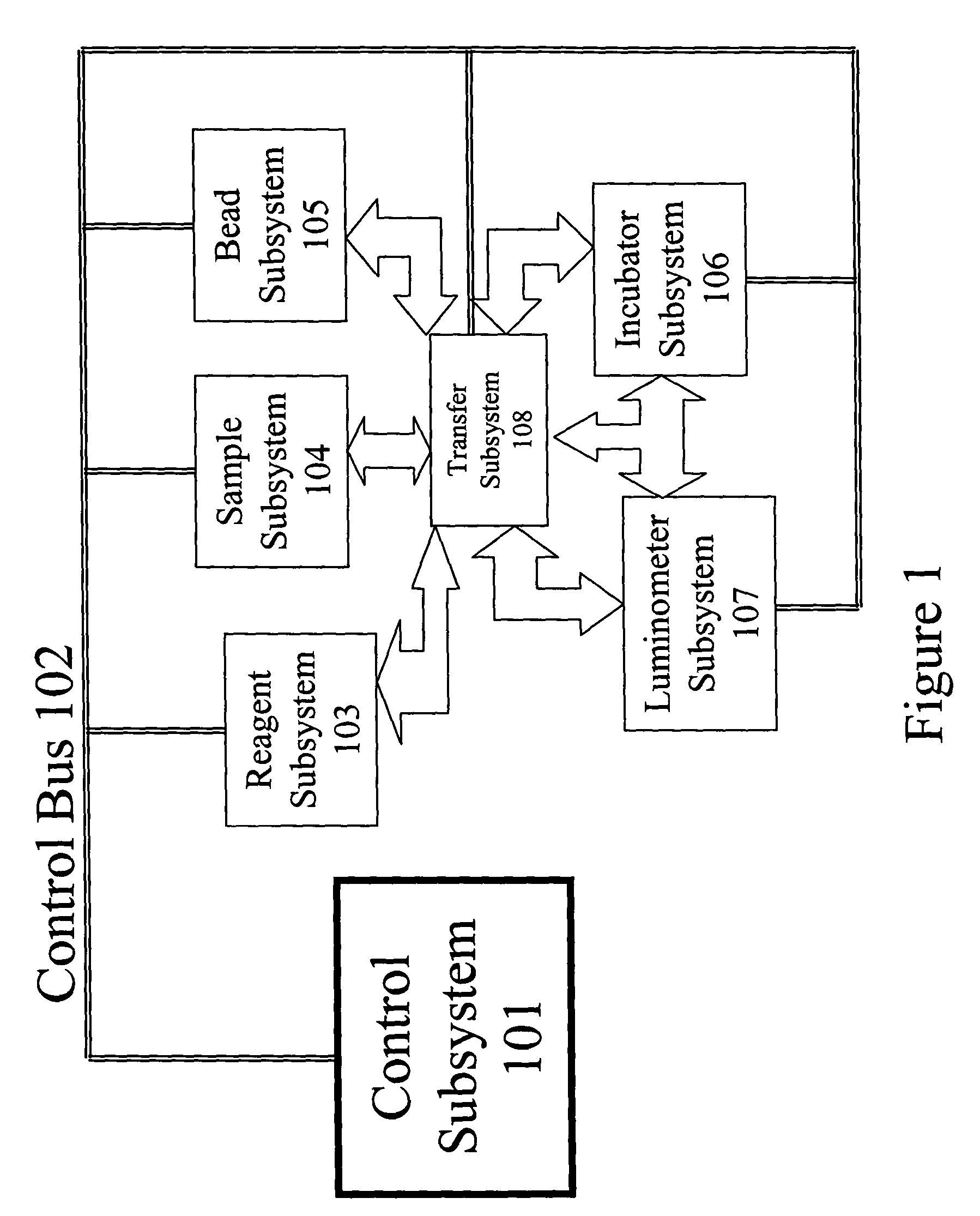
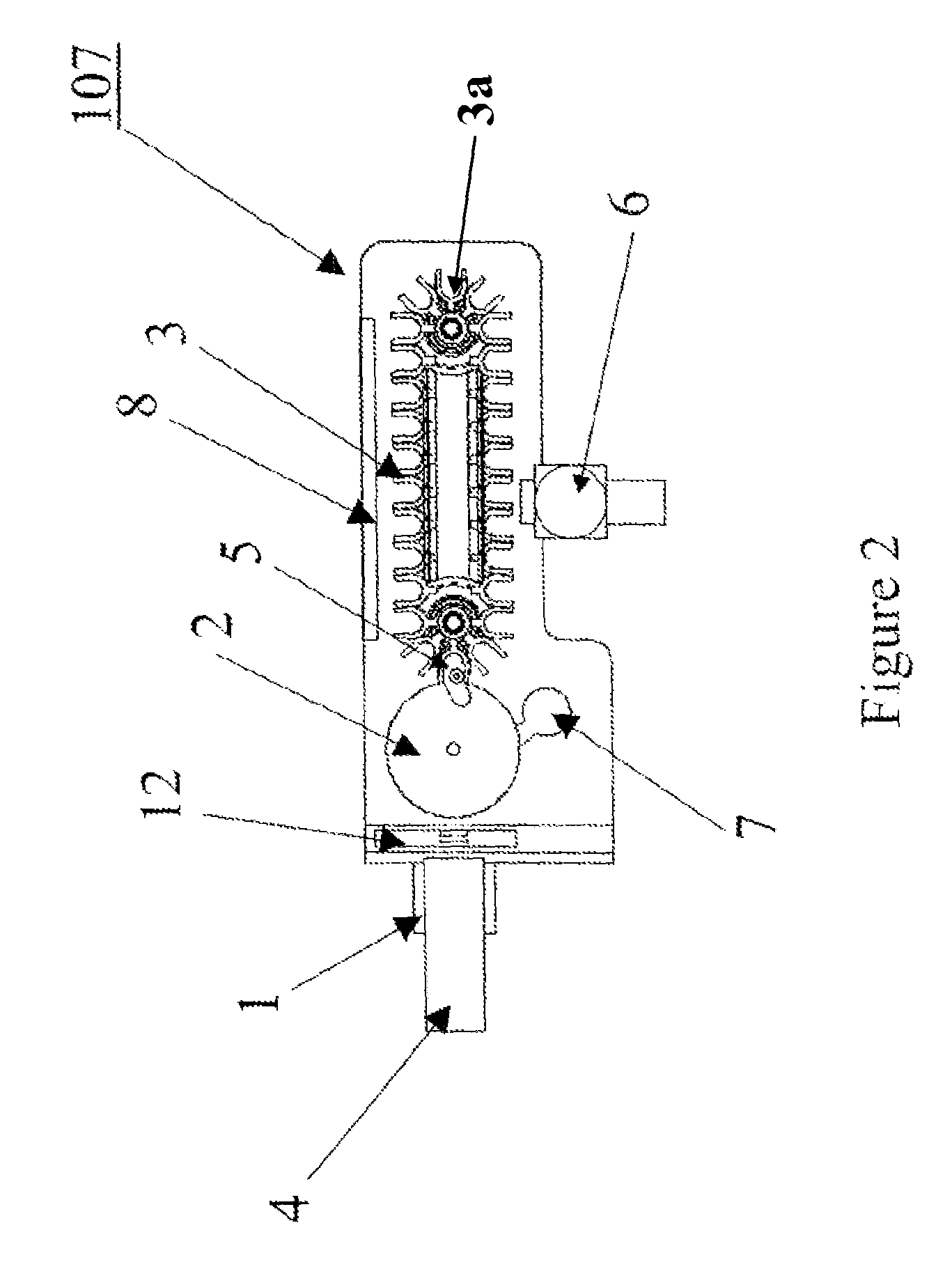
[0025]Referring now to the drawings, and more particularly to FIG. 1, which shows an automated immunoassay analyzer as a complex system with numerous subsystems that allow the tests to be performed without the continuous monitoring and intervention of a technician. The technician selects the tests to be performed for each sample and enters this information via the control subsystem 101. The control subsystem 101 manages the other subsystems by sending command and control information via the control bus 102. Samples of biological material (e.g., blood, urine, plasma, etc.) are placed by the technician in the sample subsystem 104. The samples within the sample subsystem 104 can be diluted prior to making measurements or can be tested in the undiluted state depending on direction from the control subsystem 101. The bead subsystem 105 adds the appropriate substrate having a bound “analyte binding compound” to the test vessel. Preferably, the substrate is present in the form of one or mo...


PUM

PropertyMeasurementUnit
radiant energyaaaaaaaaaa
chemiluminescenceaaaaaaaaaa
fluorescenceaaaaaaaaaa

Abstract

A rotary luminometer subsystem presents test vessels to a detection mechanism to be read as part of the automated immunoassay analyzer system. The rotary luminometer provides a read station separate from that of the transportation element of the luminometer. Within the read station, a housing and shield eliminates light leakage from the sample under test. In addition, the read station regulates the intensity of the light by providing an attenuation capability.

Description

BACKGROUND OF THE INVENTION[0001]1. Field of the Invention[0002]The present invention generally relates to a luminometer subsystem within an automated immunoassay analyzer used to quantify the analyte obtained from a test sample and, more particularly, to a subsystem that presents the reaction vessel to a detection mechanism, reads the varying light intensities that correspond to a concentration of a sample analyte to be quantified, and disposes of the analytical element and substrate after completion of a measurement.[0003]2. Background Description[0004]Automated immunoassay analyzers are being manufactured that allow a computer controlled system to analyze the amount of analyte in a sample such as blood, plasma or urine. To quantify the results, the sample is subjected to a myriad of complex processes that may include sample dilution, adding reagents, incubating, agitating, washing and reading of the sample. Reading of the sample has been performed previously using a detection mec...

Claims


Application Information

Patent Timeline
Patent Type & Authority Patents(United States)
IPC IPC(8): G01N35/02G01N21/64G01N35/00G01N35/04
CPCG01N21/645G01N21/76G01N35/0092G01N35/0095G01N35/021Y10T436/113332G01N2035/00524G01N2035/00564G01N2035/0093G01N2035/0408
Inventor MALYAROV, ILYAPALMIERI, THOMAS
Owner SIEMENS HEALTHCARE DIAGNOSTICS INC
Why Eureka
Try Eureka