Localization of a radioactive source

a radioactive source and location technology, applied in the field of location and tracking of ionizing radiation sources, can solve the problems of radioactive exposure for subjects and medical staff, and achieve the effect of reducing the biological effect of patients and/or medical personnel

Inactive Publication Date: 2011-05-31
NAVOTEK MEDICAL
View PDF134 Cites 64 Cited by
  • Summary
  • Abstract
  • Description
  • Claims
  • Application Information

AI Technical Summary

Benefits of technology

[0024]Optionally, position is determined using a sensor which has angular sensitivity resulting in a detectable change in output resulting from radiation detection according to an effective angle of incidence of radiation from the source. Greater sensitivity in effective angle of incidence provides greater efficiency of the position determination in terms of speed and accuracy. Embodiments with an angular range of less than ±100 milliradians, optionally less than ±50 milliradians are disclosed. In an exemplary embodiment of the invention, greater sensitivity to effective angle of incidence can be achieved by moving a radiation detector and / or a shield.
[0026]Optionally, the refresh rate for the location data insures that the locational information is temporally well correlated to the actual location of a tracked object (e.g. medical device). Recommended refresh rates vary according to the speed at which the tracked object moves and according to the environment in which the tracked object moves. In an exemplary embodiment of the invention, for tracking of medical devices through body parts which are more static, such as brain or digestive tract, lower refresh rates, for example 10 times / second may be adequate. In some embodiments for tracking of medical devices through body parts which move frequently, such as the heart, higher refresh rates, for example 20 times / second may be desirable. Optionally, gating to an ECG output may be implemented so that positions from selected cardiac cycle phases are plotted. Other exemplary refresh rates are higher than 30 Hz, and values intermediate 0.1 Hz, 1 Hz, 3 Hz, 10 Hz and 20 Hz.
[0028]Variables which may influence the accuracy of determined position(s) include activity of the source in DPM, the accuracy and / or response time of radiation sensors employed for detection, and the speed of the implanted medical device. Improvement in one or more of these variables may compensate for one or more other variables. Optionally, reducing the speed of a tracked medical device may be employed to compensate for other variables. Optionally, location information is displayed in the context of anatomical imaging data. Optionally, relevant anatomical features are highlighted to facilitate navigation of the medical device by medical personnel. Optionally, determined positions may be displayed in the context of a separately acquired image.
[0045]In an exemplary embodiment of the invention, the optimization allows sensor parameters to vary in a way which changes the optimal aiming of different parts of the sensor array.

Problems solved by technology

Those techniques which employ ionizing radiation, such as fluoroscopy and CT, require sufficient amounts of ionizing radiation that radiation exposure for subjects and medical staff is a subject of concern.

Method used


Image

  • Localization of a radioactive source
  • Localization of a radioactive source
  • Localization of a radioactive source

Examples


Embodiment Construction

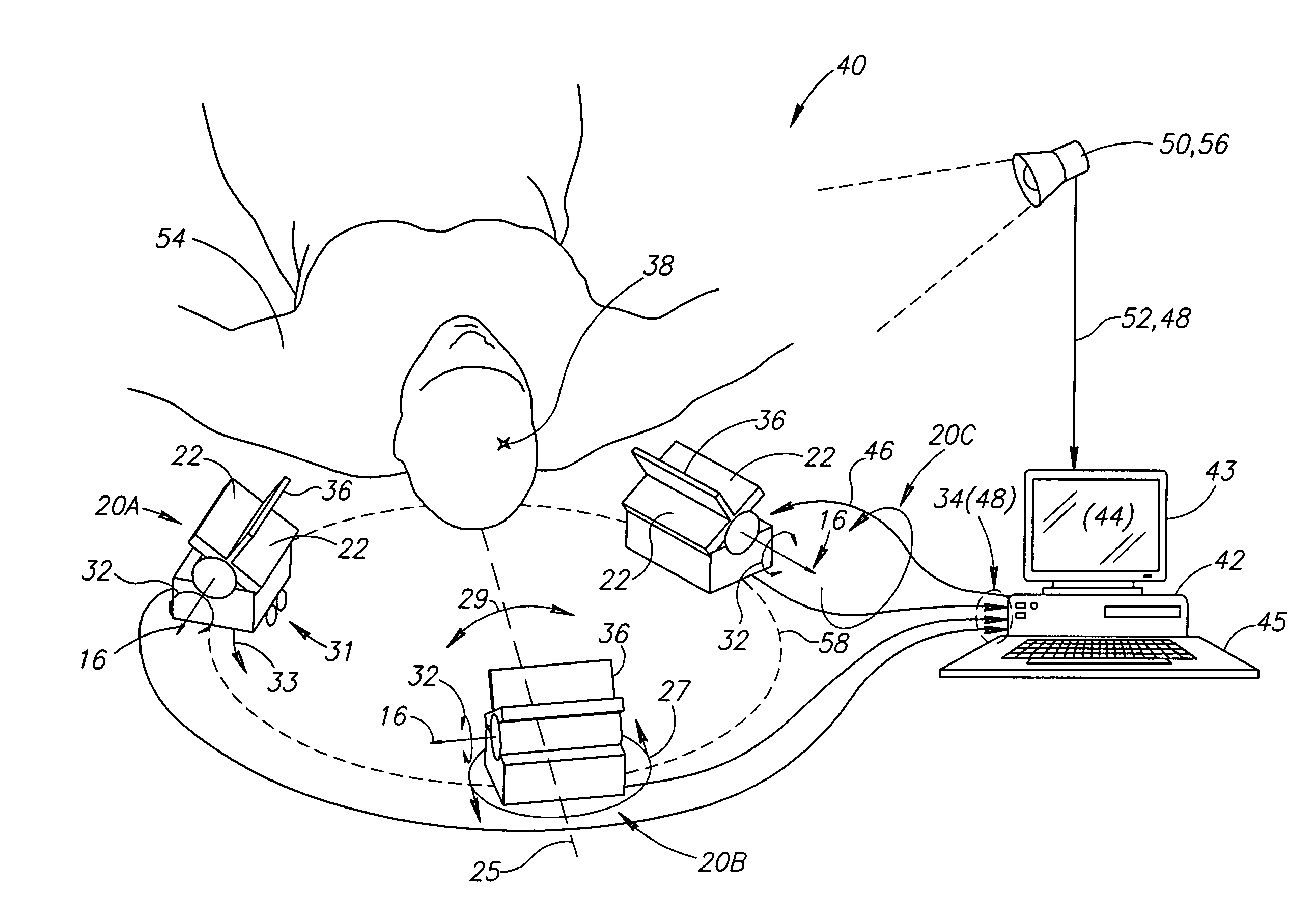
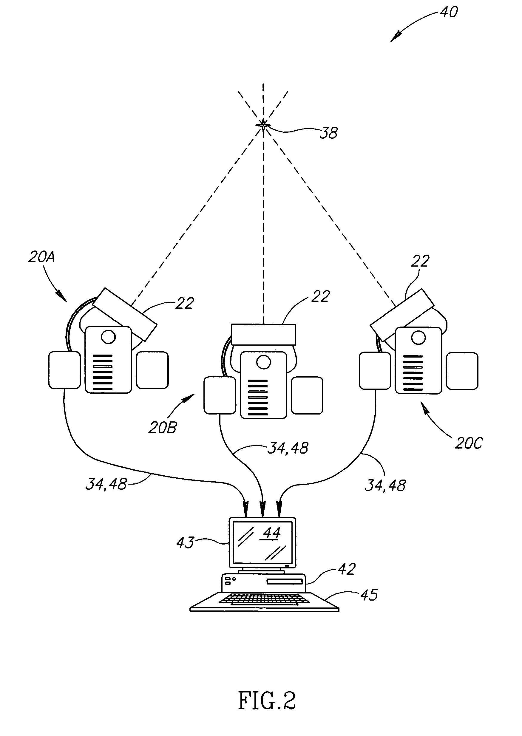
[0165]According to one embodiment of the invention (FIGS. 2 and 4), a computerized system 40 locates and / or tracks a device. In the embodiment depicted in FIG. 4, the device is a medical device. Medical devices include, but are not limited to, tools, implants, navigational instruments and ducts. Tools include, but are not limited to, catheters, canulae, trocar, cutting implements, grasping implements and positioning implements. Implants include, but are not limited to, brachytherapy seeds, stents and sustained release medication packets. Navigational instruments include, but are not limited to, guidewires. Ducts include, but are not limited to, tubing (e.g. esophageal tubes and tracheal tubes). In exemplary embodiments of the invention, one or more moving tools are tracked.

[0166]In an exemplary embodiment of the invention, position of the source is determined by non-imaging data acquisition. For purposes of this specification and the accompanying claims, the phrase “non-imaging” ind...


PUM


Abstract

An angle-responsive sensor, comprising:a radiation detector adapted to detect ionizing radiation;at least one radiation absorbing element arranged to block radiation from reaching said detector in a manner dependent on a relative orientation of a radiation source, said detector and said element, said detector and said element defining an aim for said sensor; andcircuitry coupled to said detector and which generates an output signal which varies as a function of said relative orientation,wherein said detector and said element are arranged to have a working volume of at least 10 cm in depth and having an angular width, such that said signal defines an accuracy of better than 3 mm within one standard deviation, over said working volume.

Description

RELATED APPLICATIONS[0001]This Application is a National Phase of PCT Patent Application No. PCT / IB2006 / 052770 having International Filing Date of Aug. 10, 2006, which claims benefit under §119(e), directly or indirectly, from U.S. Provisional Applications Nos.:[0002]60 / 773,931 filed on Feb. 16, 2006, entitled “Radiation Oncology Application”;[0003]60 / 804,178 filed on Jun. 8, 2006, entitled “Radioactive Medical Implants”;[0004]60 / 773,930 filed Feb. 16, 2006, entitled “Localization of a Radioactive Source”;[0005]The disclosures of these applications are fully incorporated herein by reference.[0006]PCT Patent Application No. PCT / IB2006 / 052770 is also a continuation-in-part of:[0007]PCT / IL2005 / 000871 filed on Aug. 11, 2005, entitled “Localization of a Radioactive Source within a Body of a Subject” which claims benefit under §119(e), from U.S. Provisional Applications Nos.:[0008]60 / 600,725 filed on Aug. 12, 2004, entitled “Medical Navigation System Based on Differential Sensor”;[0009]60...

Claims


Application Information

Patent Timeline
Patent Type & Authority Patents(United States)
IPC IPC(8): A61B19/00A61B6/12
CPCA61B19/52A61B19/5244A61B19/54A61B6/4258G01T1/2907A61B5/1127A61B2019/207A61B2019/5251A61B2019/5268A61B2019/542A61B2019/505A61B34/20A61B90/36A61B90/39A61B2034/105A61B2034/2051A61B2034/2068A61B2090/101A61B2090/392
Inventor NEUSTADTER, DAVID MAIERKORNBLAU, GIORA
Owner NAVOTEK MEDICAL
Why Eureka
Try Eureka