Time multiplexed space switch

a space switch and time division technology, applied in the field of time division multiplexing of data channels, can solve the problems of conventionally considered problematic, delaying channel tributaries, and difficult implementation of time switching in the optical domain, and achieves the effects of reducing the number of optical gates, facilitating tributary switching, and high quality pulses

a space switch and time division technology, applied in the field of time division multiplexing of data channels, can solve the problems of conventionally considered problematic, delaying channel tributaries, and difficult implementation of time switching in the optical domain, and achieves the effects of reducing the number of optical gates, facilitating tributary switching, and high quality pulses

US7953323B2Inactive Publication Date: 2011-05-31ZARRIS GEORGE

Image

  • Time multiplexed space switch
  • Time multiplexed space switch
  • Time multiplexed space switch

Examples


Embodiment Construction

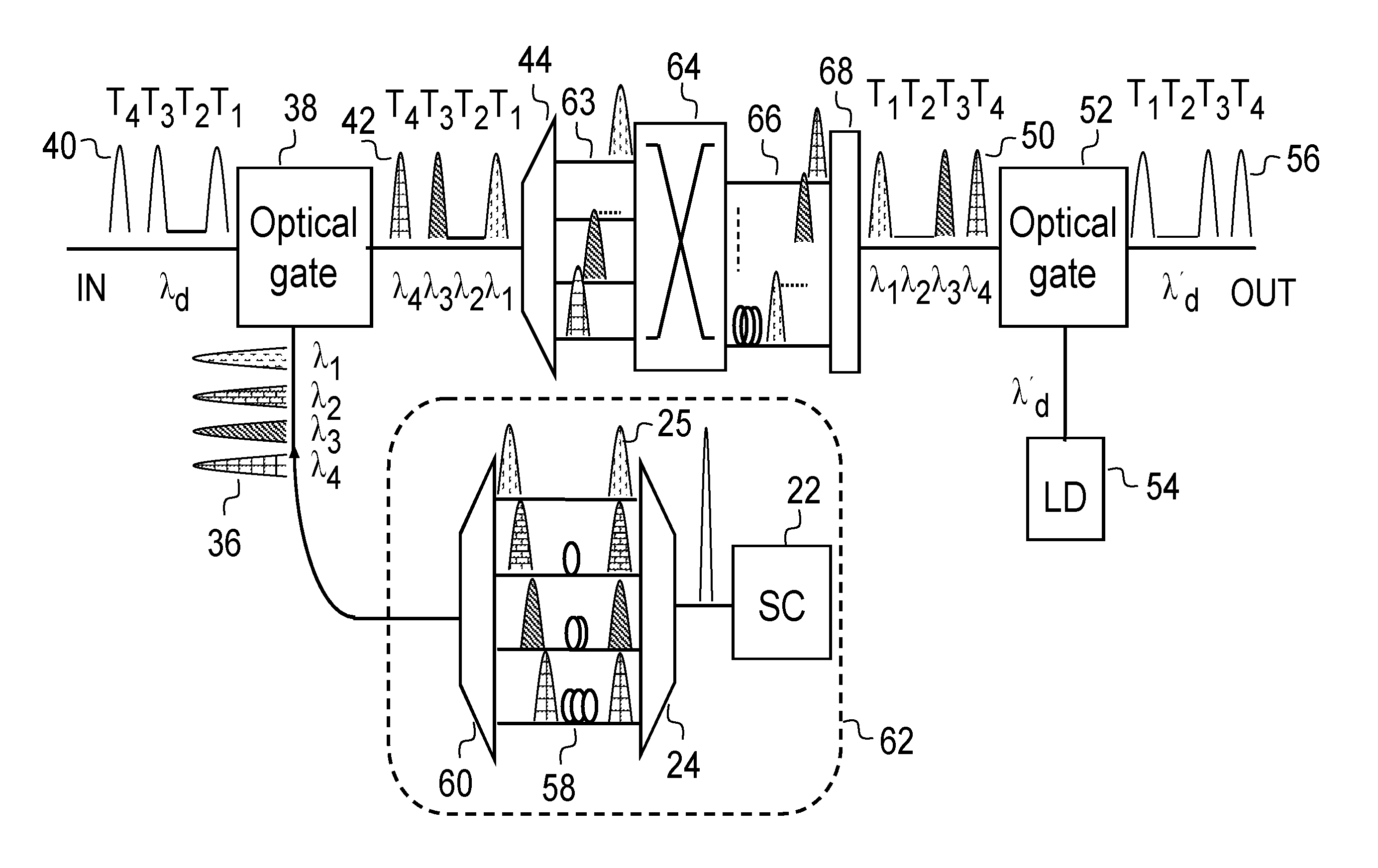
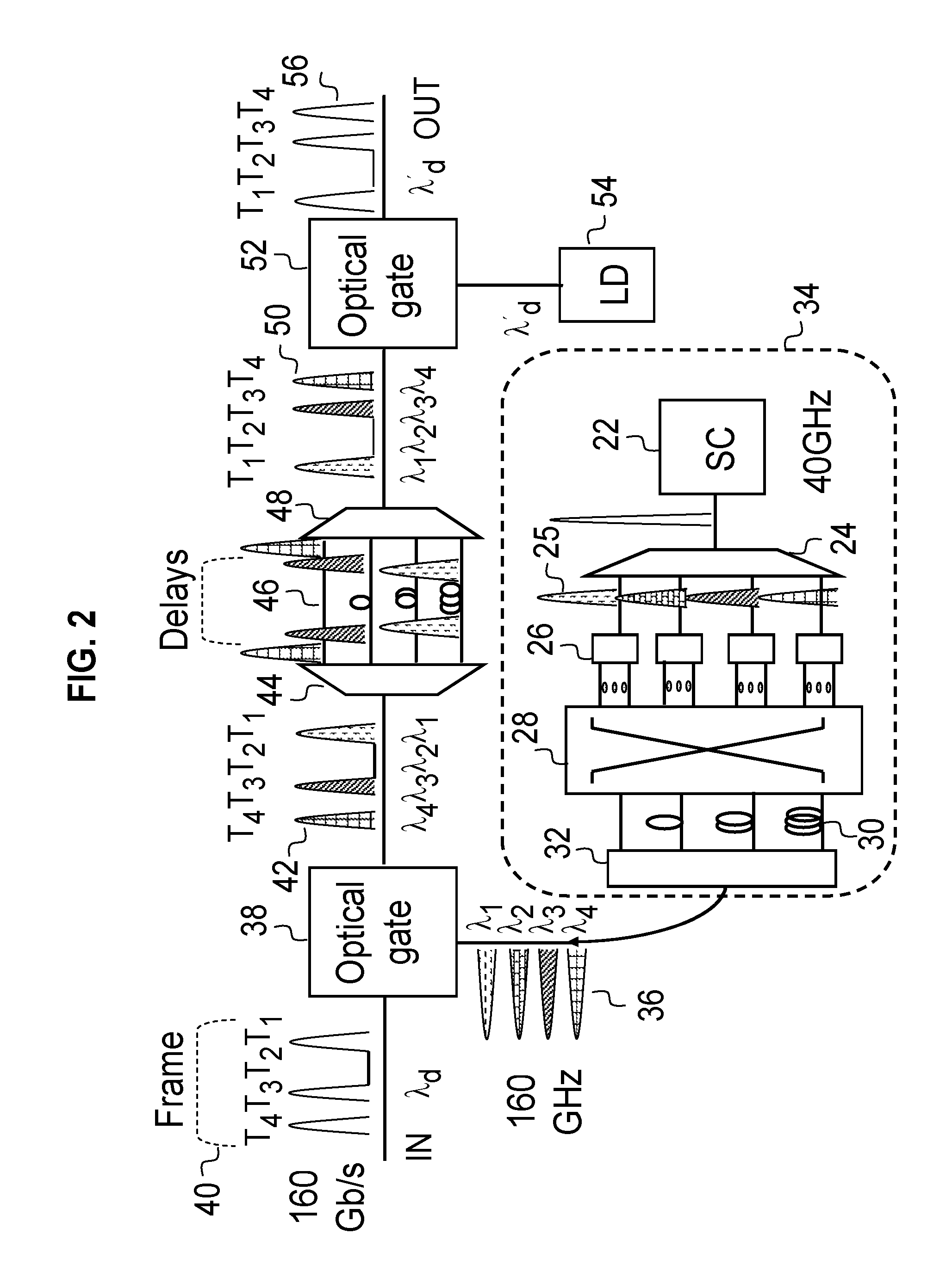
In FIG. 2, a laser source 22 of ultra-short pulse radiation (SC) produces a sequence of pulses of rate equal to the data tributary rate (say, 40 GHz), and is spectrally sliced, using a wavelength de-multiplexer 24, to produce a number of synchronous pulse sequences 25 (in this case, four) each at different wavelength. Subsequently, each pulse is split into a number of pulses of same wavelength using a power splitter 26. A space switch 28 selects a number of thus produced pulses and blocks and discards the pulses which are not needed. Each of the selected pulses is connected by the switch to a delay line 30 of appropriate time delay. In this example the four delay paths differ in delay by one bit period of the higher rate TDM data channel (160 Gb / s). A coupler 32 combines the delayed pulses. In this way, a multi-wavelength pulse sequence 36 is created of 160 GHz rate (4 times 40 GHz), which can be altered by re-configuring the space switch 28. Therefore, the system 34 is a pulsed las...


PUM


Abstract

The present invention provides an optical time multiplexed space switch including a pulsed laser source, and means for producing from the laser source a plurality of wavelengths of pulsed radiation including means for providing permutable multi-wavelength pulse sequences from said multi-wavelength source and means for translating the input data pulses into the multi-wavelength pulse sequence. Each data pulse is subsequently guided through a wavelength selective structure, which may contain delay lines. In the case of time-slot interchange, the pulses are recombined in an interchanged sequence. In the case of tributary space switching different wavelength pulses are switched to generally different outputs and combine with pulses originating from different inputs. Alternatively, instead of or in addition to the means for providing permutable multi-wavelength pulse sequences from the pulsed source, means are provided for the permutation of the multi-wavelength data pulse sequence in reconfigurable wavelength selective structures.

Description

BACKGROUNDThe present invention relates to time division multiplexing of data channels and in particular to time division multiplexing and switching of bit-interleaved digital communication channels by optical techniques. The present invention is particularly applicable to communications switching systems in the core communication network.There is considerable interest today in ultra-high speed optical transmission. For example, 100 Gigabit per second Ethernet is considered to be the next big leap in transmission and networking from the metro to the core or backbone network. Even with the application today of wavelength division multiplexing, also know as WDM, which increases the data transmission capacity of an optical fiber by one or two orders of magnitude, there is interest in transmitting ultra-high bit-rate channels for economic as well as networking reasons. First, reducing the number of interfaces, or ports, in the core network at the wavelength level may bring economic bene...

Claims


Application Information

Patent Timeline
31 May 2011
Publication
US7953323B2
IPC
H04J14/00
CPC
H04J14/02; H04J14/08; H04J14/083; H04Q11/0005; H04Q2011/0041; H04Q2011/0016; H04Q2011/002; H04Q2011/0033
Inventors
ZARRIS, GEORGE