
Method of controlling aircraft, missiles, munitions and ground vehicles with plasma actuators

a technology of plasma actuators and actuators, which is applied in the direction of airflow influencers, instruments, transportation and packaging, etc., can solve the problems of increasing the noise and vibration of the airframe, the drag penalty of these traditional control surfaces is very high, and the use of movable control surfaces, etc., to reduce the power requirements of aircraft, missiles, munitions and ground vehicles. , to increase the efficiency of aircraft, missiles, munitions and ground vehicles

Active Publication Date: 2011-06-07
ORBITAL RES
View PDF4 Cites 16 Cited by
  • Summary
  • Abstract
  • Description
  • Claims
  • Application Information

AI Technical Summary

Benefits of technology

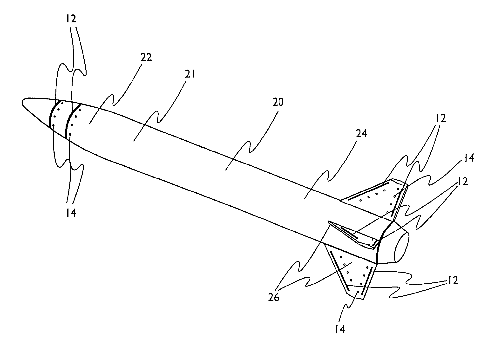
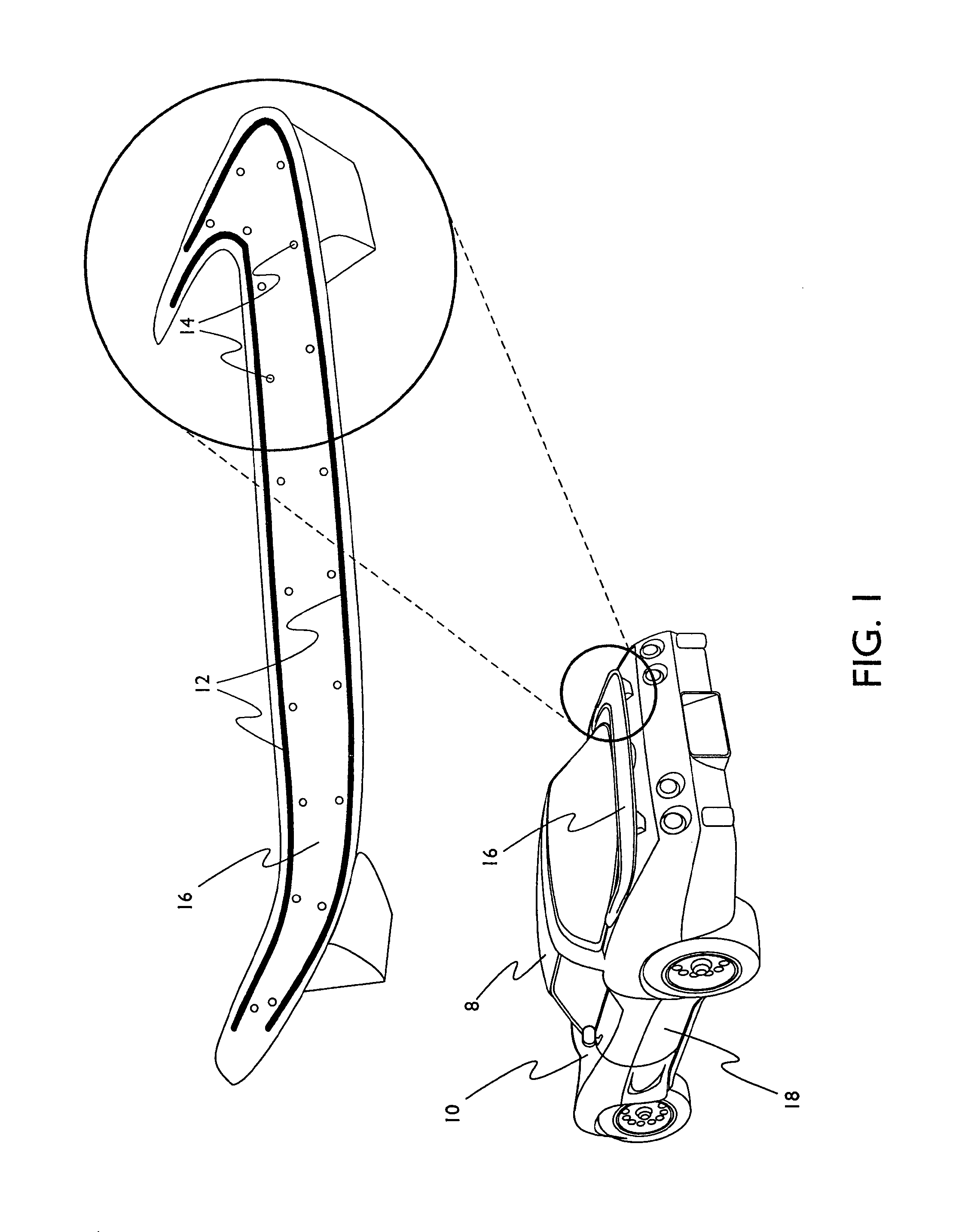
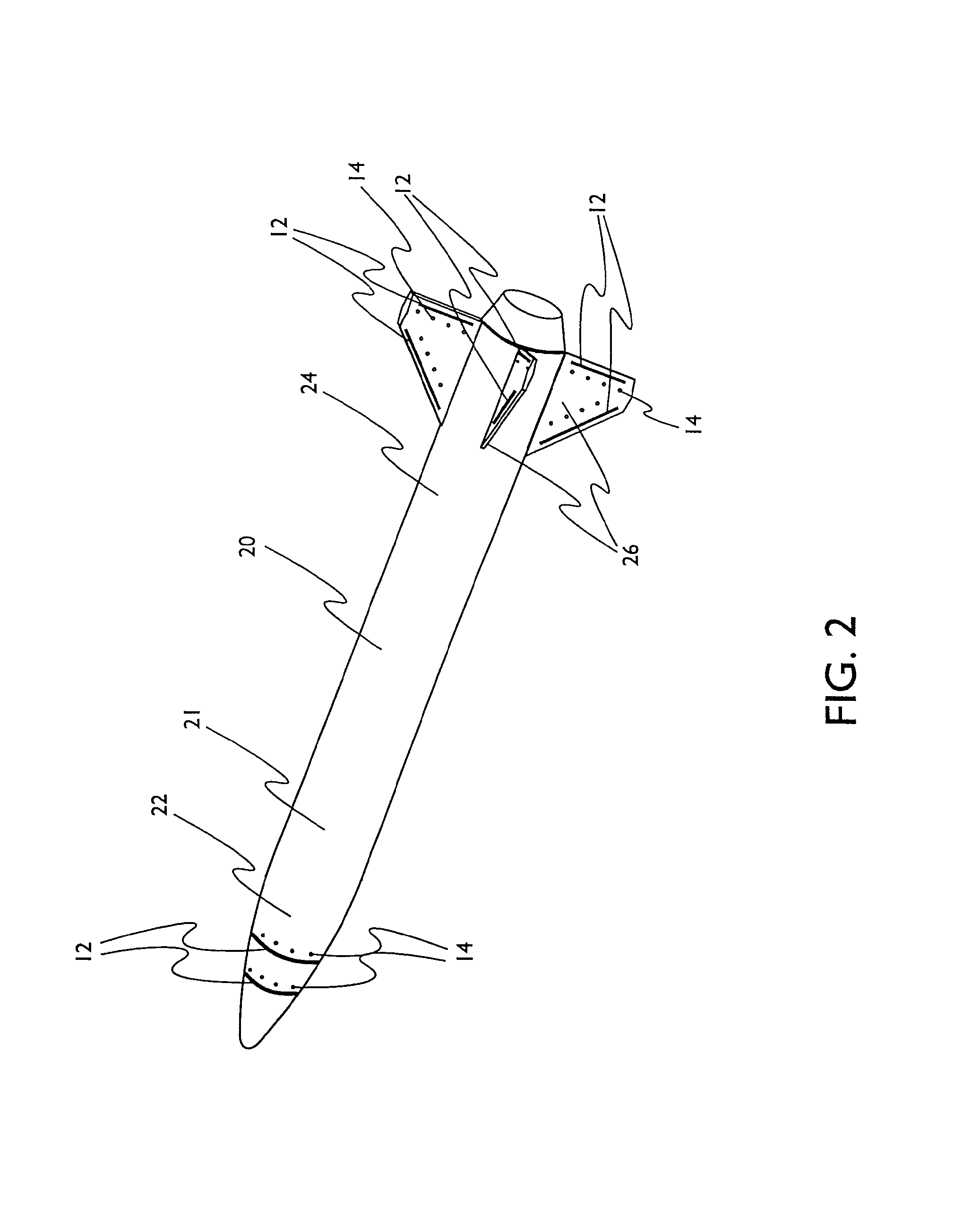
The present invention relates to a method of controlling an aircraft, missile, munition, or ground vehicle with plasma actuators for the purpose of controlling airflow separation over a control surface. The method includes designing an aerodynamic plasma actuator for the purpose of controlling airflow separation over a control surface of a vehicle, measuring or estimating the velocity of fluid flowing past the surface, and activating the plasma actuator at a frequency equal to the velocity of the fluid divided by the placement distance of the actuator from the trailing edge or aft end. The method provides a means for increasing the efficiency of these vehicles and reducing their power requirements.

Problems solved by technology

While the benefits of these conventional types of control surfaces are well documented, it is also known that the use of movable control surfaces increase airframe noise and vibration, particularly at high deflection angles.
With these types of surfaces, most of the noise originates from the separated flow in the gap or hinge regions which contribute to the drag component of the viscous drag on the control surface.
At off design conditions, the drag penalty from these traditional control surfaces is very high.
Another drawback with traditional control surfaces is that motors or pneumatics are required, which add volume, weight, and costs to these types of systems.

Method used


Image

  • Method of controlling aircraft, missiles, munitions and ground vehicles with plasma actuators
  • Method of controlling aircraft, missiles, munitions and ground vehicles with plasma actuators
  • Method of controlling aircraft, missiles, munitions and ground vehicles with plasma actuators

Examples


Embodiment Construction

[0024]The present invention relates to a method of controlling an aircraft, missile, munition or ground vehicle with plasma actuators, and more particularly to controlling fluid flow across their surfaces or other surfaces, which would benefit from such a method. The method includes the design of an aerodynamic plasma actuator for the purpose of controlling airflow separation over a control surface of a aircraft, missile, or a ground vehicle, and more particularly to the method of determining a modulation frequency for the plasma actuator for the purpose of fluid flow control over these vehicles.

[0025]The method involves a number a number of steps. Depending on particular embodiments of the method, the method could include one or more of the following steps, but is not limited to only these steps. Possible steps are: locating or placing a plasma actuator; measuring or estimating the free stream velocity of fluid flowing past the surface on which the plasma actuator is located; locat...


PUM


Abstract

A method of controlling an aircraft, missile, munition or ground vehicle with plasma actuators, and more particularly of controlling fluid flow across their surfaces or other surfaces which would benefit from such a method, includes the design of an aerodynamic plasma actuator for the purpose of controlling airflow separation over a control surface of a aircraft, missile, or a ground vehicle, and a method of determining a modulation frequency for the plasma actuator for the purpose of fluid flow control over these vehicles. Various embodiments provide steps to increase the efficiency of aircraft, missiles, munitions and ground vehicles. The method of flow control reduces the power requirements of the aircraft, missile, munition or ground vehicle. These methods also provide alternative aerodynamic control using low-power hingeless plasma actuator devices.

Description

CROSS REFERENCE TO RELATED APPLICATION[0001]This application is a continuation of U.S. patent application Ser. No. 11 / 415,535 filed May 2, 2006 that issued on Dec. 1, 2009 as U.S. Pat. No. 7,624,941.[0002]The U.S. Government has a paid-up license in this invention and the right in limited circumstances to require the patent owner to license others on reasonable terms provided for by the terms of grants F33615-03-M-3327 and FA8650-04-C-3405 awarded by the U.S. Air Force, AFRL, Air Vehicles Directorate, Wright-Patterson Air Force Base.BACKGROUND OF THE INVENTION[0003]1. Field of the Invention[0004]The present invention relates to a method of controlling an aircraft, missile, munition or ground vehicle with plasma actuators, and more particularly to controlling fluid flow across their surfaces or other surfaces, which would benefit from such a method. The method includes the design of an aerodynamic plasma actuator for the purpose of controlling airflow separation over a control surfac...

Claims


Application Information

Patent Timeline
Patent Type & Authority Patents(United States)
IPC IPC(8): B64C23/00B64C21/00F42B15/01
CPCB62D35/007B64C23/005F42B10/668F42B10/40Y02T50/166Y02T10/82Y02T50/10B64C2230/12F42B10/38
Inventor PATELCORKE, THOMAS C.
Owner ORBITAL RES
Learn More