Contactless transmission of a differential signal between a transmitter and a receiver

a technology of differential signal and transmission channel, which is applied in the direction of instruments, waveguide type devices, optical elements, etc., can solve the problems of affecting the transmission quality, affecting the operation of the transmission channel, so as to achieve the effect of suppressing the common-mode interference effect and optimum common-mode noise signal suppression

Active Publication Date: 2011-06-07
SIEMENS HEALTHCARE GMBH
View PDF4 Cites 2 Cited by
  • Summary
  • Abstract
  • Description
  • Claims
  • Application Information

AI Technical Summary

Benefits of technology

[0014]For example, the ground reference potential of the receiver is divided or separated, into two areas. The two areas are decoupled from one another. The common-mode interference or the common-mode noise signal or signals may fall at the point of this division or a corresponding separation point such that the portion of the common-mode interference which falls at the input of the differential amplifier in the receiver is reduced. The two ground reference potentials, or ground potentials, are divided into two potentials, which can be referred to for example as “Ground” (GND) and “Receiver Ground” (RX-GND). Through this separation, an effective common-mode noise signal suppression is achieved when choosing suitable areas for the division. The differential useful signal to be transmitted, such as a wideband high-frequency signal, can be transmitted without major disruption with regard to the clock and data recovery.
[0015]Alternatively or additionally, a filter unit at an input of a receive amplifier may suppress common-mode noise signals. The filter unit may be a passive filter unit, which attenuates at least one common-mode noise signal present in a coupler for coupling at least one signal from the transmitter to the receiver at least essentially to the same extent as a signal of the same frequency to be transmitted. Alternatively or additionally, in order to suppress common-mode interference effects, a ground reference potential relating to a part of the receiver including a receive amplifier can be capacitively coupled to a ground reference potential of the transmitter.
[0037]Between the two antenna lines exists a surface whose potential does not depend on the excitation by the differential useful signal. If a conductive structure is placed into this surface, then this has no influence on the transmission of the common-mode signals since no currents flow within this surface on account of the potential, which is the same everywhere. Accordingly, the structure of a coupler can be placed into this surface, as a result of which an additional coupling of the ground potentials is achieved without any degradation of the quality of transmission of the useful signal.
[0038]The capacitive coupling can be combined with the use of the filter unit or the division of the ground reference potentials in order to achieve an overall optimum common-mode noise signal suppression. The capacitive coupling suppresses common-mode interference effects.
[0045]The circuit arrangement can have at least one optocoupler and / or transducer and / or optoelectrical converter with optical waveguide designed for the separation of at least one signal. Optocouplers and / or transducers are to be recommended in this situation, as has already been described above, for the separation of low-frequency signals, whereas in the case of high-frequency signals such as digital useful signals having high data rates optoelectrical converters in conjunction with optical waveguides enable a separation which is comparatively simple to implement.

Problems solved by technology

The contactless wideband transmission of differential high-frequency signals between a transmitter and a receiver, such as the two different modules, may have relatively strong and low-frequency common-mode interference effects, which impair the quality of transmission.
If the working range of the amplifier input is exceeded, then errors occur with a frequency, which is no longer tolerable in the case of a data signal to be transmitted with regard to the subsequent clock or data recovery.
The danger that the permissible working range of the amplifier input will be exceeded exists if the straight-symmetric signal portion, such as the common-mode signal becomes too great at the input of the differential amplifier.
A first cause may be imbalances in the output stages of the line drivers can cause common-mode interference effects.
A second cause may be an imbalance in the coupling, for example, as a result of positioning errors or manufacturing tolerances, can bring about a common-mode signal correlated with a useful signal.
A third cause for the occurrence of common-mode interference (so-called common-mode signal) is a mismatch of potential between the ground reference systems of the transmitter and receiver in the case of unequal reference systems.
If a tolerable level is exceeded, an error-free clock and data recovery or a clock and data recovery, which is errored up to a tolerable extent, is no longer possible.
A suppression by the differential amplifier is not possible.
A satisfactory clock and data recovery can also be endangered as a result.
The common-mode interference effects caused by the voltage between the two ground potentials can exceed the useful signal amplitude by orders of magnitude, such that the signal quality drops intolerably as a result of the then unavoidable overdriving of the amplifier input.

Method used


Image

  • Contactless transmission of a differential signal between a transmitter and a receiver
  • Contactless transmission of a differential signal between a transmitter and a receiver
  • Contactless transmission of a differential signal between a transmitter and a receiver

Examples


Embodiment Construction

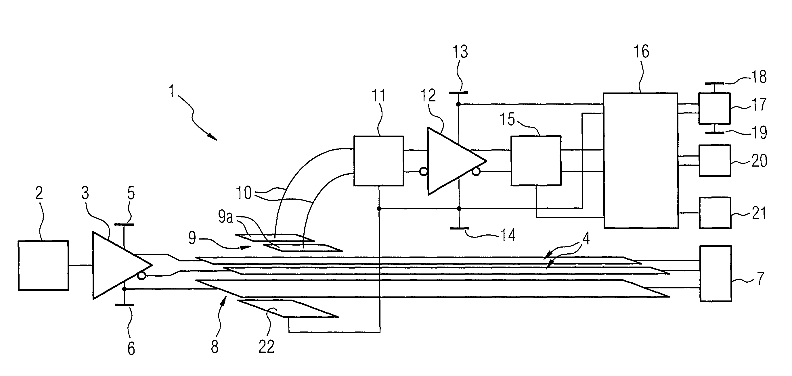
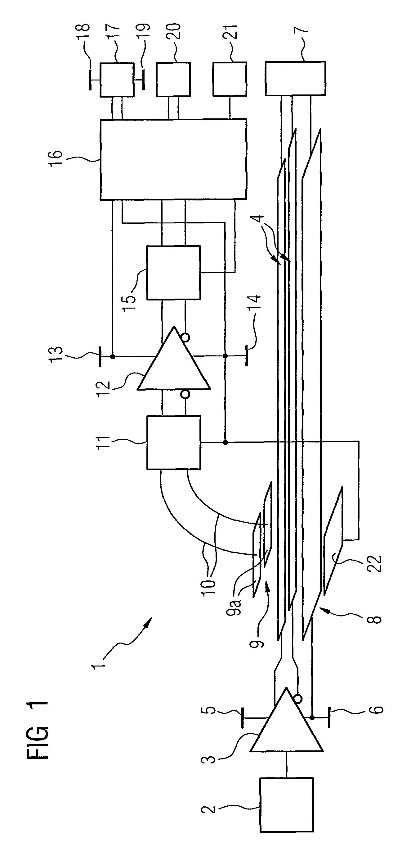
[0054]FIG. 1 shows a circuit arrangement 1 for executing a method.

[0055]This circuit arrangement 1 has a signal source 2, from which the signal or signals are fed with the aid of a line driver 3 as a differential driver with the polarity inverted with respect to one another into an antenna 4 with two inputs. The positive supply voltage 5 and the ground reference potential TX-GND 6 (ground reference potential of the transmitter) beside the supply voltage 5 are assigned to the line driver 3.

[0056]The antenna 4 is a homogeneous double line which has at its end a termination 7. The homogeneous double line of the antenna 4 is terminated by the termination 7 with the characteristic impedance. The signal is fed as described in differential mode into the antenna 4.

[0057]In the embodiment described here a further line 8 with the ground reference potential of the transmitter is taken in a homogeneous manner, for example, with geometric dimensions and material properties which are constant ove...


PUM


Abstract

A method for the contactless transmission of at least one differential signal between a transmitter and a receiver given the existence of at least one common-mode noise signal, which has a low frequency in comparison with at least one signal to be transmitted, is provided. The suppression of at least one common-mode noise signal within the receiver a ground reference potential assigned to the receiver is separated into two ground reference potentials decoupled from one another. At least one common-mode noise signal may be suppressed by a filter unit at the input of a receive amplifier of the receiver.

Description

[0001]This patent document claims the benefit of German Patent Application No. DE 10 2007 048 164.2 filed on Oct. 8, 2007, which is hereby incorporated by reference.BACKGROUND[0002]The present embodiments relate to contactless transmission of at least one differential signal between a transmitter and a receiver given the existence of at least one common-mode noise signal. In particular, the present embodiments may relate to contactless transmission of at least one common-mode noise signal, which has a low frequency in comparison with at least one signal to be transmitted.[0003]Data or signals may be transmitted in contactless fashion between modules. For example, in medical technology, a computer tomography has a rotating part and a stationary part, between which data is transmitted.[0004]The contactless wideband transmission of differential high-frequency signals between a transmitter and a receiver, such as the two different modules, may have relatively strong and low-frequency co...

Claims


Application Information

Patent Timeline
Patent Type & Authority Patents(United States)
IPC IPC(8): H01P5/08G02B6/42H04B1/40
CPCG08C15/08H04L25/0294H04B5/0012
Inventor HEMMERLEIN, MARKUSREPP, HELMUT
Owner SIEMENS HEALTHCARE GMBH
Why Eureka
Try Eureka