
X-ray radiography for container inspection

Active Publication Date: 2011-06-07
NORTHRUP GRUMMAN SPACE & MISSION SYST CORP +1
View PDF17 Cites 22 Cited by
  • Summary
  • Abstract
  • Description
  • Claims
  • Application Information

AI Technical Summary

Benefits of technology

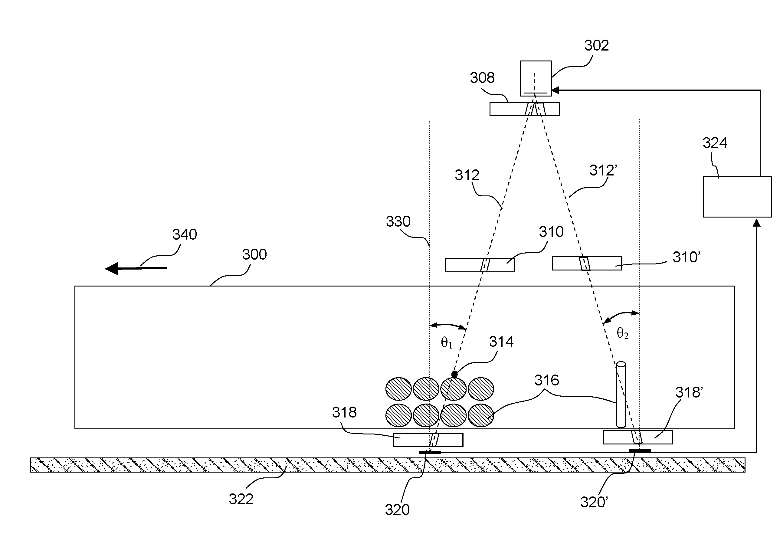
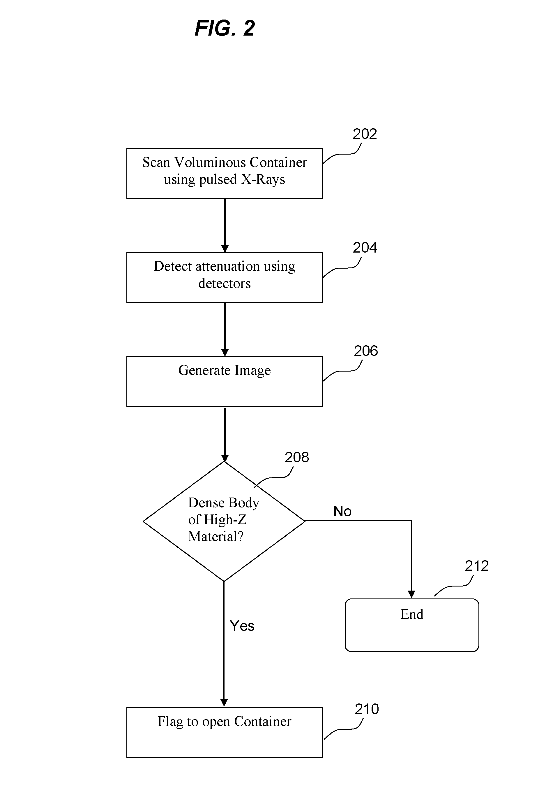
[0006]According to a first broad aspect of the present invention, there is provided an inspection method comprising: generating a radiographic image based on a detected attenuation corresponding to a plurality of pulsed beams of radiation transmitted through a voluminous object; and determining that there is a high-z material in the voluminous object based on a localized high attenuation in the generated radiographic image, wherein the plurality of pulsed beams of radiation are transmitted substantially downward along an incident angle to a vertical axis extending through the voluminous object.
[0007]According to a second broad aspect of the invention, there is provided an inspection device for inspecting a voluminous object comprising: a high-energy source for generating a first set of pulsed beams of radiation, wherein the plurality of pulsed beams of radiation are transmitted substantially downward along an incident angle to a vertical axis extending through the voluminous object; means for discriminating against scattered radiation from the plurality of pulsed beams of radiation that are transmitted through the voluminous object; means for generating a radiographic image based on detected attenuation corresponding to the plurality of pulsed beams of radiation transmitted through the voluminous object; and means for determining that a high-z material exists in the

Problems solved by technology

The detonation of a nuclear weapon in a major city is perhaps the worst terrorist threat imaginable, with casualties and property damage likely exceeding those of past terrorist attacks by a factor of ten or a hundred or even more.
The shipping and transportation industry is considered at risk for terrorist activity due to the high volume of containers that moved across borders and low inspection rates.
Since existing inspection methods are insufficient in detecting the presence of nuclear weapons, each of the containers must be opened and inspected manually.
Inspecting each container manually would be time consuming and cause major delays.

Method used


Image

  • X-ray radiography for container inspection
  • X-ray radiography for container inspection
  • X-ray radiography for container inspection

Examples


example 1

[0042]FIG. 5 is a computer model radiographic image obtained by detecting a 5 kg sphere of 6-plutonium (r=0.0422 m) at the center of a container uniformly filled with iron to a density of 300 kg / m3. This model is based on using an X-ray source is a beam of 10 MeV electrons which radiate bremsstrahlung when stopped by a 7 mm thick tungsten converter slab at a height of 5.2 m above the top of the container using a layout as shown in FIGS. 3A and 3B. Below the converter there is a 10 mm wide slot collimator made of tungsten 0.1 m thick. A similar slot collimator above the container matches a 10 mm wide detector array. The detectors are modeled as a transverse row of point sensors 0.2 m below the container, spaced 10 mm apart, which respond to the X-ray energy flux, a fair approximation to the behavior of several practical scintillators. A final Bucky collimator between the container and the detectors consists of a 0.16 m thick slab of tungsten with holes of 5 mm diameter bored along th...

example 2

[0044]Many containers will contain pockets of innocent dense medium-Z material (large castings such as engine blocks, ingots, rod stock, etc.), and a terrorist may fill the empty space in a voluminous container with such objects in order to disguise a dense piece of fissionable material. Radiography must identify, or exclude the presence of, a threat in such a cluttered environment. FIG. 6 therefore shows the radiograph of a 5 kg sphere of 6-plutonium (r=0.0422 m) at the center of a very cluttered container. In addition to the threat object, it contains 230 spheres of half-density iron that model an automotive engine block, with internal voids, each 0.20 m in radius, totaling 30 MT. The iron spheres arc in planar square arrays, 0.50 m apart, 0.55 m and 1.05 m below the container's midplane.

[0045]If the direction of irradiation were vertical the plutonium sphere would not be detectable because the line of sight through it would pass through the centers of two of the iron spheres, for...


PUM


Abstract

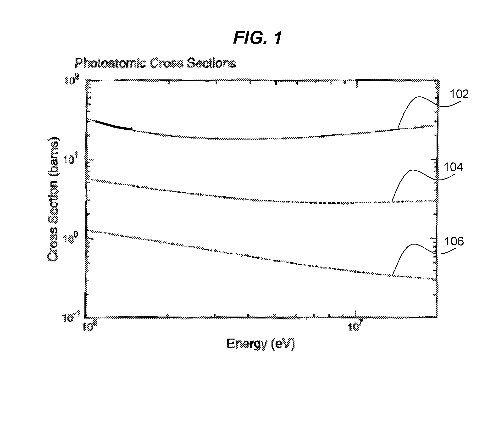
Arrangements of X-ray inspection systems are described for inspecting high-z materials in voluminous objects such as containers. Inspection methods may involve generating a radiographic image based on detected attenuation corresponding to a pulsed beams of radiation transmitted through a voluminous object. The pulsed beams of radiation are generated by a high-energy source and transmitted substantially downward along an incident angle, of approximately 1° to 30°, to a vertical axis extending through the voluminous object. The generated radiographic image may be analyzed to detect on localized high attenuation representative of high-z materials and to discriminate high-z materials from lower and intermediate-z materials on the basis of the high density and greater attenuation of high-z material for higher energy (3-10 MeV) X-rays, and the compact nature of threatening masses of fissionable materials.

Description

GOVERNMENT INTEREST STATEMENT[0001]The United States Government has rights in this invention pursuant to Contract No. DE-AC52-06NA25396 between the United States Department of Energy / National Nuclear Security Administration and the Los Alamos National Security LLC for the operation of the Los Alamos National Laboratory.BACKGROUND[0002]1. Field of the Invention[0003]The present invention relates generally to X-ray radiography, and more particularly relates to radiation inspection devices and methods for detecting the presence of high-z materials in containers.[0004]2. Related Art[0005]The detonation of a nuclear weapon in a major city is perhaps the worst terrorist threat imaginable, with casualties and property damage likely exceeding those of past terrorist attacks by a factor of ten or a hundred or even more. The shipping and transportation industry is considered at risk for terrorist activity due to the high volume of containers that moved across borders and low inspection rates....

Claims


Application Information

Patent Timeline
IPC IPC(8): G01B15/02G21K1/02G21K1/00
CPCG01B15/00G21K1/025G01V5/0091G01B15/025G01V5/281
Inventor KATZ, JONATHAN I.MORRIS, CHRISTOPHER L.
Owner NORTHRUP GRUMMAN SPACE & MISSION SYST CORP
Learn More