Unlock instant, AI-driven research and patent intelligence for your innovation.

Moving image coding apparatus, moving image decoding apparatus, control method therefor, and computer-readable storage medium

a coding apparatus and moving image technology, applied in the field of moving image data coding technique, can solve the problems of resultant error differing from the original value, and difficulty in effectively reducing the code amount, so as to prevent deterioration in image quality and suppress errors

Inactive Publication Date: 2011-06-07
CANON KK
View PDF53 Cites 7 Cited by
  • Summary
  • Abstract
  • Description
  • Claims
  • Application Information

AI Technical Summary

Benefits of technology

This approach effectively suppresses the accumulation of errors in predicted frame images, ensuring improved image quality and efficient code data generation while maintaining scalability, even in varying processing environments.

Problems solved by technology

For this reason, it is difficult to effectively reduce the code amount as compared with the moving image coding scheme using time correlation.
When the above MPEG coding scheme is to be applied to a scheme designed to perform bitplane coding so as to realize scalability as in JPEG 2000, errors in motion compensation due to abortion of bitplane coding are accumulated to cause a deterioration in image quality.
In addition, if a rounded-down lower bitplane is compensated for by 0, the resultant error differs from the original value.
If a P-picture or B-picture is generated from a P-picture in MPEG, errors are accumulated, resulting in a deterioration in the image quality of a moving image.

Method used


Image

  • Moving image coding apparatus, moving image decoding apparatus, control method therefor, and computer-readable storage medium
  • Moving image coding apparatus, moving image decoding apparatus, control method therefor, and computer-readable storage medium
  • Moving image coding apparatus, moving image decoding apparatus, control method therefor, and computer-readable storage medium

Examples


first embodiment

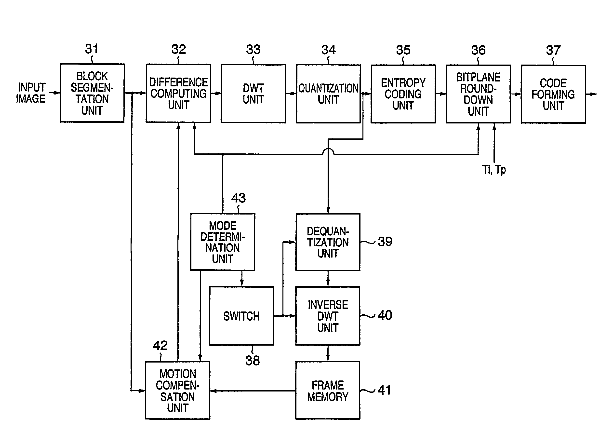
[0039]FIG. 1 is a block diagram showing the arrangement of a moving image coding apparatus according to the first embodiment. In the first embodiment, as an image coding scheme to be used by the moving image coding apparatus, the Motion JPEG 2000 coding scheme will be described as an example. However, the present invention is not limited to this.

[0040]Referring to FIG. 1, reference numeral 31 denotes a block segmentation unit which segments input image data into blocks; 32, a difference computing unit which obtains the difference between the image data and predicted data obtained by motion compensation (to be described later) for the image data; 33, a DWT unit which performs discrete wavelet transformation for the segmented blocks; 34, a quantization unit which quantizes the transformation coefficients obtained by discrete wavelet transformation; 35, an entropy coding unit which performs EBCOT coding based on the JPEG 2000 coding scheme for each bitplane; 36, a bitplane round-down u...

second embodiment

[0073]FIG. 3 is a block diagram showing the arrangement of a moving image coding apparatus according to the second embodiment of the present invention. The same reference numerals as in FIG. 1 denote the parts having the same functions in FIG. 3, and a description thereof will be omitted.

[0074]Referring to FIG. 3, reference numeral 1414 denotes a frame memory which stores input image data; 142, a motion compensation unit which performs motion prediction from data from the frame memory 1414 and an input image and calculates a motion vector and predicted data; and 143, a switch which controls its output in accordance with an output from a mode determination unit 43. Upon receiving a signal indicating the intra-frame coding mode, the switch 143 overwrites each input block on the frame memory 1414. Upon receiving a signal indicating the inter-frame coding mode, the switch 143 is turned off and any data is not written in the frame memory 1414. With this operation, the image data of an in...

third embodiment

[0093]The third embodiment will be described next. FIG. 5 is a block diagram showing the arrangement of a moving image coding apparatus according to the third embodiment.

[0094]Referring to FIG. 5, reference numeral 300 denotes a central processing unit (CPU) which controls the overall apparatus and performs various types of processing; 301, a memory which provides an operating system (OS) required to control this apparatus, a computer program for image compression processing, and a storage area for arithmetic operation; and 402, a bus which connects various kinds of devices to each other to exchange data and control signals.

[0095]Reference numeral 303 denotes an input unit comprising switches for issuing instructions to start up the apparatus, set various kinds of conditions, and play back, and a pointing device such as a keyboard or mouse (trademark); 304, a storage device (e.g., a hard disk) which stores the above OS and various kinds of software; and 305, a storage device which s...


PUM


Abstract

In this invention, even if final code data is to be generated by selectively discarding code data for each bitplane, errors due to bitplane rounding down operation can be suppressed from being gradually accumulated in predicted data such as P- and B-pictures, thereby preventing a deterioration in image quality. For this purpose, a block segmentation unit (31) segments an input frame into a plurality of blocks, and supplies the respective blocks to a difference computing unit (32). The difference computing unit (32) outputs the blocks to a DWT unit (33) without any change when the intra-frame coding mode is set. When the inter-frame coding mode is set, the difference computing unit (32) outputs the result obtained by computing a difference from predicted data from a motion compensation unit (42) to the DWT unit (33). The frequency component data obtained by the DWT unit (33) and a quantization unit (34) is entropy-coded by an entropy coding unit (35), and a bitplane formed by bit information at the bit position of each component value is coded. A bitplane round-down unit (36) rounds down the code data of bitplanes from the least significant position to an upper bit position such that the resultant code amount becomes equal to or less than a target code amount. A code forming unit then generates code data. Only when the intra-frame coding mode is set, a dequantization unit (39) and inverse DWT unit (40) are executed to update a frame memory (41).

Description

[0001]This application is a National Stage Filing Under 35 U.S.C. ยง371 of International Application No. PCT / JP2005 / 004850, filed Mar. 11, 2005, and published in English as International Publication No. WO 2005 / 088976 on Sep. 22, 2005, which claims priority to Japanese Patent Application Nos. 2004-071399, filed Mar. 12, 2004 and 2005-015847, filed Jan. 24, 2005, hereby incorporated by reference.TECHNICAL FIELD[0002]The present invention relates to a coding technique for moving image data.BACKGROUND ART[0003]Recently, contents flowing on networks, the Internet in particular, have increased in volume and diversity from character information to still image information, further to moving image information. Accordingly, coding techniques for compressing information amounts have been developed. The developed coding techniques have been standardized internationally and widely spread.[0004]On the other hand, networks themselves have increased capacity and diversity, and hence one content fro...

Claims


Application Information

Patent Timeline
Patent Type & Authority Patents(United States)
IPC IPC(8): G06K9/36H04N7/12G06K9/46H04B1/66H04N11/02H04N11/04H04N19/50H03M7/36H04N19/102H04N19/134H04N19/146H04N19/159H04N19/177H04N19/34H04N19/503H04N19/513H04N19/60H04N19/61H04N19/63H04N19/85H04N19/91
CPCH04N19/63
Inventor SUZUKI, MASAKIMAEDA, MITSURU
Owner CANON KK