
Method for producing geogrid

a geogrid and production method technology, applied in the field of geogrid, can solve the problems of deterioration of installation resistance, deterioration of structural stability, and likely damage to textile geogrids, and achieve the effects of improving installation resistance, excellent shape stability, and increasing resistance to vertical load

Inactive Publication Date: 2011-06-14
SAMSANG CORP
View PDF30 Cites 2 Cited by
  • Summary
  • Abstract
  • Description
  • Claims
  • Application Information

AI Technical Summary

Benefits of technology

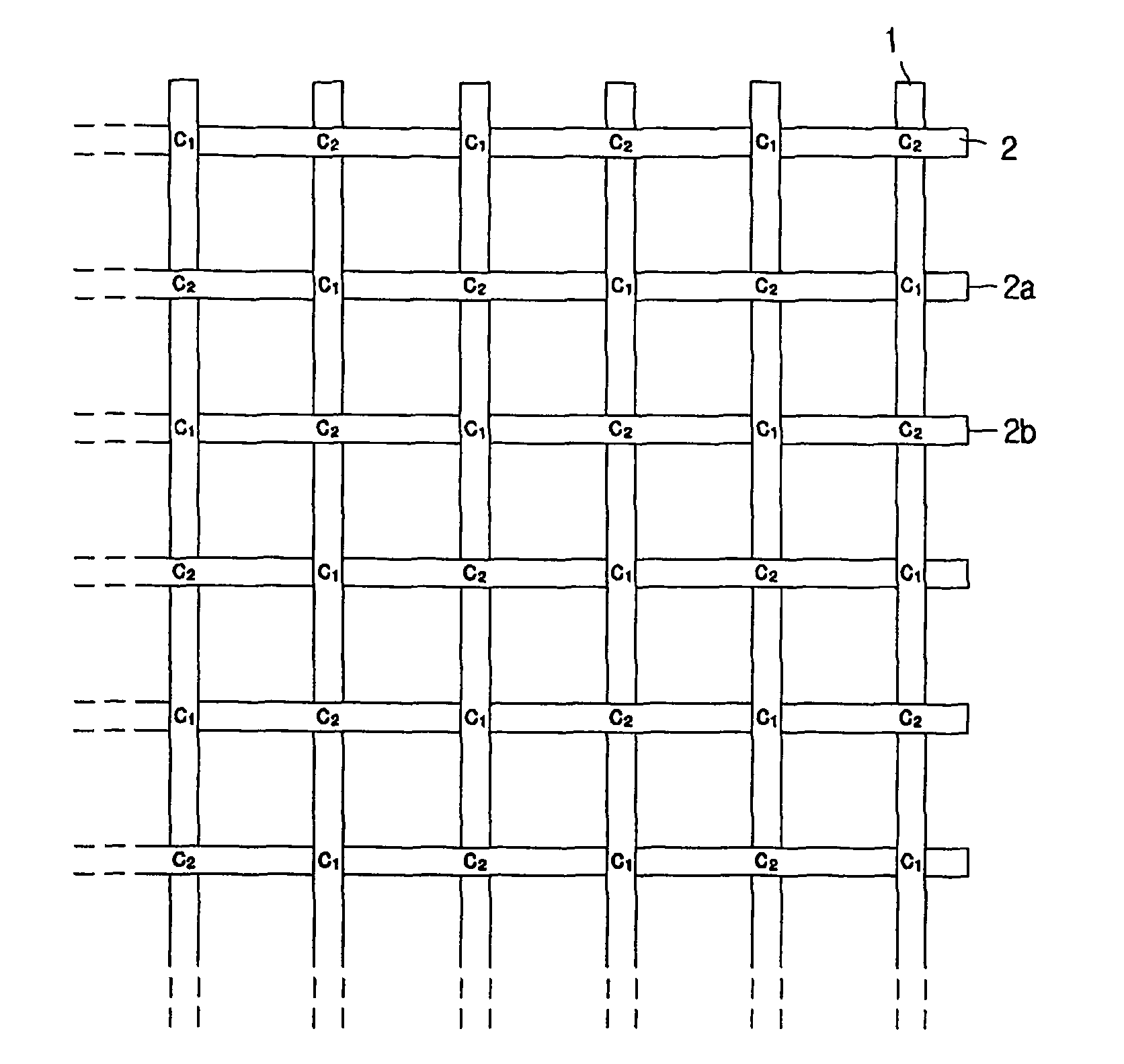
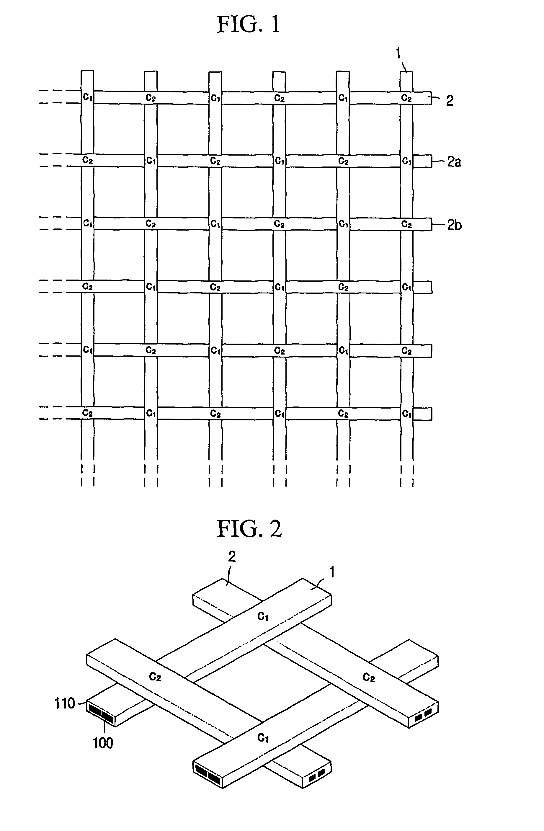
The present invention provides a geogrid that has high tensile strength, low tensile strain, and low creep strain, as well as excellent resistance to installation damage, friction behavior, and shape stability. The geogrid includes longitudinal fiber-reinforced polymer strips and lateral fiber-reinforced polymer strips arranged in a plain weave structure, with alternating contact points on their surfaces. The thermoplastic polymer resin of the longitudinal and lateral fiber-reinforced polymer strips is welded and fixed at the contact points, which increases resistance against vertical load and frictional force with a reinforced material such as soil. The geogrid is produced at a low cost and can be mass-produced.

Problems solved by technology

However, the plastic geogrid shows serious creep strain when a load is applied for a long time thereto due to its material characteristics, thereby possibly causing deterioration of structural stability.
However, the textile geogrid is likely to be damaged depending on the state of soil in construction, so installation resistance is deteriorated.
In addition, the textile geogrid is also not economically desirable since the producing procedure is too complex.
However, if the fiber-reinforced polymer strips are adhered in such a way, the fibers existing in the polymer may be damaged to deteriorate their tensile properties, and perfect adhesion between the strips is substantially not realized since the longitudinal and lateral polymer strips are not all in a melted state.
In addition, since the geogrid in the aforementioned document has a flat structure, the geogrid has inferior friction behavior and unsatisfactory shape stability against a vertical load.

Method used


Image

  • Method for producing geogrid
  • Method for producing geogrid
  • Method for producing geogrid

Examples


embodiment 1

[0102]A polyester high-tenacity fiber bundle of 48000 deniers is passed through a nipple having a rectangular section and through a rectangular die to make a longitudinal fiber-reinforced polymer strip having a section shown in (a) of FIG. 11a with a width of 8.4 mm and a thickness of 2.3 mm. In addition, a lateral fiber-reinforced polymer strip having the same section as the longitudinal fiber-reinforced polymer strip with a width of 6.3 mm and a thickness of 1.5 mm is made with the use of polyester high-tenacity fiber bundle of 20000 deniers. Polypropylene having a melt index of 4 is used as a thermoplastic polymer resin. Then, the longitudinal fiber-reinforced polymer strips are arranged on the strip arranging unit so that a product width is 4 m and a distance between the strips is 40 mm, and then the lateral fiber-reinforced polymer strips are inserted at an interval of 50 mm to have an angle of 90° with the longitudinal strip, thereby making a lattice having a plain weave struc...

embodiment 2

[0103]Two polyester high-tenacity fiber bundles of 24000 deniers are passed through a two-hole nipple having a rectangular section and through a rectangular die to make a longitudinal fiber-reinforced polymer strip having a section shown in (b) of FIG. 11a with a width of 8.4 mm and a thickness of 2.3 mm. In addition, a lateral fiber-reinforced polymer strip having the same section as the longitudinal fiber-reinforced polymer strip with a width of 6.3 mm and a thickness of 1.5 mm is made with the use of two polyester high-tenacity fiber bundles of 10000 deniers. Then, the strips are arranged in the same way as the first embodiment to produce a geogrid. The number of ribs per unit length (ribs / m), a wide-width tensile strength (kN / m), LASE5% (kN / m). a tensile strain (%), a creep strain (%) and a strength reduction rate (%) under construction of the produced geogrid are shown in the following table 1.

embodiment 3

[0104]Three polyester high-tenacity fiber bundles of 16000 deniers are passed through a three-hole nipple having a rectangular section and through a rectangular die to make a longitudinal fiber-reinforced polymer strip having a section shown in (c) of FIG. 11a with a width of 8.4 mm and a thickness of 2.3 mm. In addition, a lateral fiber-reinforced polymer strip having the same section as the longitudinal fiber-reinforced polymer strip with a width of 6.3 mm and a thickness of 1.5 mm is made with the use of four polyester high-tenacity fiber bundles of 5000 deniers. Then, the strips are arranged in the same way as the first embodiment to produce a geogrid. The number of ribs per unit length (ribs / m), a wide-width tensile strength (kN / m), LASE5% (kN / m), a tensile strain (%), a creep strain (%) and a strength reduction rate (%) under construction of the produced geogrid are shown in the following table 1.


PUM

PropertyMeasurementUnit
crossing angleaaaaaaaaaa

Abstract

A geogrid using fiber-reinforced polymeric strips and its producing method are disclosed. The geogrid of a lattice shape includes plural longitudinal fiber-reinforced polymeric strips longitudinally arranged in parallel at regular intervals and formed by reinforcing fiber in a thermoplastic polymer resin, and plural lateral fiber-reinforced polymer strip laterally arranged in parallel at regular intervals and formed by reinforcing fiber in a thermoplastic polymer resin. Each longitudinal fiber-reinforced polymer strip has at lease one first contact point crossed with the lateral fiber-reinforced polymer strip on the upper surface and at least one second contact point crossed with the lateral fiber-reinforced polymer strips on the lower surface. The contact points are fixed by welding the longitudinal and lateral fiber-reinforced polymer strips. The geogrid is excellent in installation capacity, frictional feature and shape stabilisation and shows high tensile strength and low tensile strain and low creep deformation.

Description

TECHNICAL FIELD[0001]The present invention relates to a geogrid mainly used as a reinforcing material and its producing method.BACKGROUND ART[0002]A geogrid is commonly used for reinforcement of soil retaining wall, slope and weak ground in the civil engineering works. The geogrid needs to have some properties such as resistance to installation damage, friction feature and shape stability in addition to high tensile strength, low tensile stain and low creep strain. The geogrid is classified into plastic geogrid and textile geogrid according to its material and producing method.[0003]The plastic geogrid is produced by passing a polymer sheet, extruded through an extruder, between rollers to perforate holes at regular intervals and then elongating the polymer sheet by one or two axes (see GB 19890020843), or produced by making lateral strips and longitudinal strips, which are made by extrusion-elongating polymer resin in a strip shape, into a flat lattice shape and then adhering the s...

Claims


Application Information

Patent Timeline
Patent Type & Authority Patents(United States)
IPC IPC(8): B29C65/00B32B37/00G01M1/00B29C48/06B29C48/07D03D1/00D03D15/02D03D41/00D04H3/04D04H3/14E02D17/18E02D17/20
CPCB29C47/0016B29C47/025B29C66/73921B29C66/8322E02D17/202D04H3/14D04H3/04D03D41/008B29C47/28B29C65/02B29C65/06B29C66/21B29C66/69B29C66/721B29C66/80B29C66/81433B29D28/005D03D1/00D03D15/0088D03D15/02D03D41/00B29C66/71B29C66/72141B29C66/7212Y10T442/133Y10T442/10Y10T442/134B29C66/7315B29K2995/0083Y10T442/183Y10T442/102B29C65/405D10B2505/204D10B2505/02B29C65/08B29C65/10B29C65/18B29C65/40B29K2105/101B29L2028/00B29L2031/737B29K2307/04B29K2077/00B29K2309/08B29K2277/10B29K2025/04B29K2069/00B29K2067/006B29K2027/06B29K2305/00B29K2309/14B29C66/43B29C66/1122B29C66/73161B29C48/06B29C48/154B29C48/34B29C48/07D03D15/46B29K2067/003B29K2033/20B29K2033/08B29K2025/06B29K2023/00B29K2009/00
Inventor YUN, KWANG-JUNGCHO, SEONG-HOCHA, DONG-HWANCHOI, SE-WHAN
Owner SAMSANG CORP
Learn More