

Hydrogen production by a thermochemical water splitting cycle
a technology of thermochemical water and water splitting, applied in the direction of separation process, electrochemical generator, energy input, etc., can solve the problems of consuming fossil fuels, electricity, and producing unwanted carbon dioxid
- Summary
- Abstract
- Description
- Claims
- Application Information
AI Technical Summary
Benefits of technology
Problems solved by technology
Method used
Image

Examples
example 1
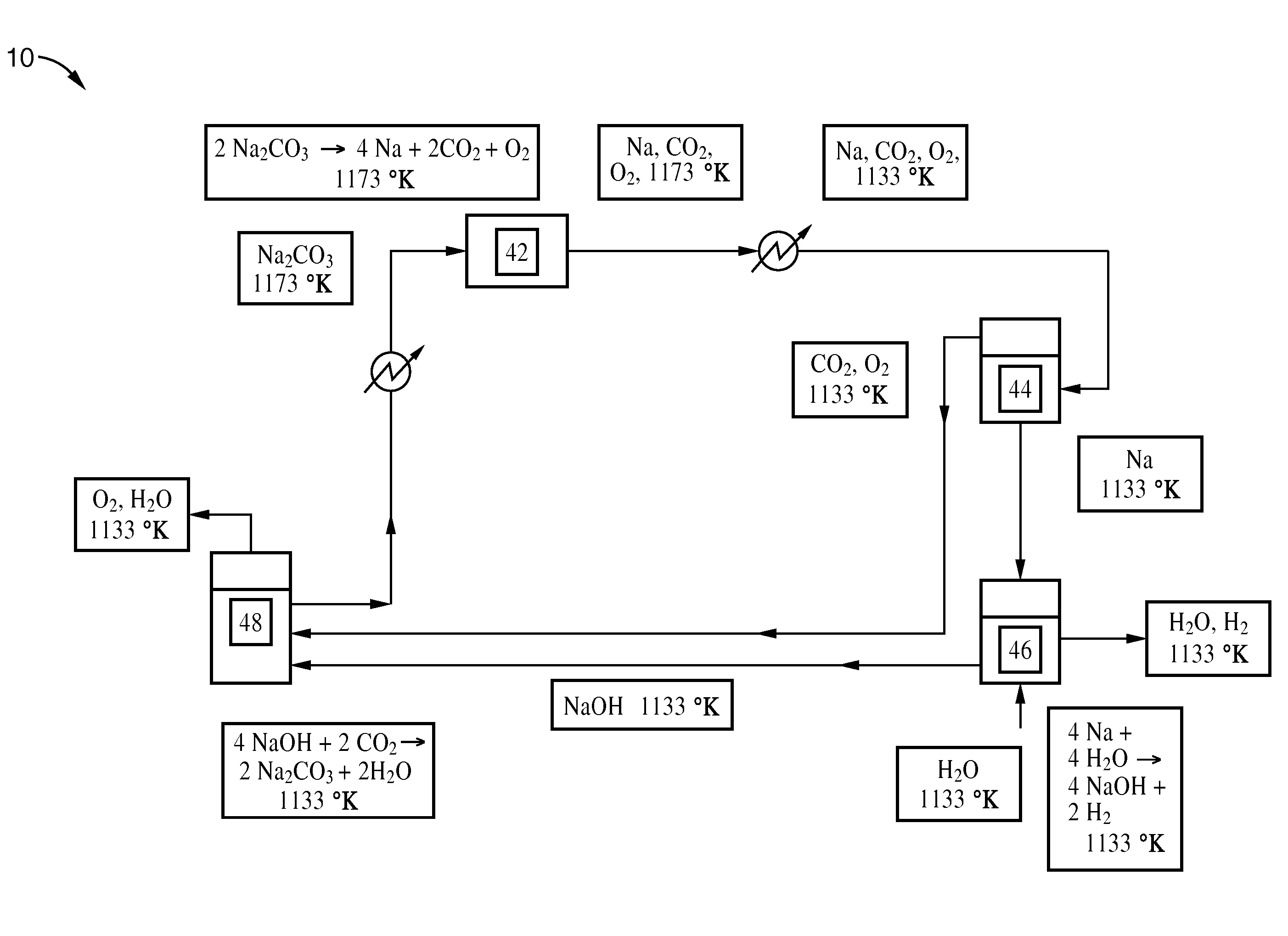
[0027]One embodiment of the thermochemical cycle can involve sodium, sodium bicarbonate, sodium carbonate, sodium hydride, sodium hydroxide, sodium monoxide, and carbon dioxide as intermediates.
2Na2CO3→4Na+2CO2+O2 (2)
4Na+4NaOH→4Na2O+2H2 (3)
4Na2O+4H2O→8NaOH (4)
4NaOH+2CO2→2Na2CO3+2H2O (5)
[0028]A process according to this embodiment is shown in FIG. 1.
[0029]Sodium carbonate is first placed in vessel 22 and heated. The sodium carbonate decomposes to a gaseous mixture of sodium, oxygen, and carbon dioxide. The gas mixture is then cooled to liquefy the sodium. The mixture enters vessel 24, where separation takes place. The sodium is sent to vessel 26, where it reacts to completion with sodium hydroxide (molten) to produce sodium monoxide and hydrogen (gas). The sodium monoxide is sent to vessel 28, where it is placed in contact with water to form sodium hydroxide.
[0030]Some of the sodium hydroxide from vessel 28 is recycled back to vessel 26 to react with the sodium and to facilitate ...
example 2
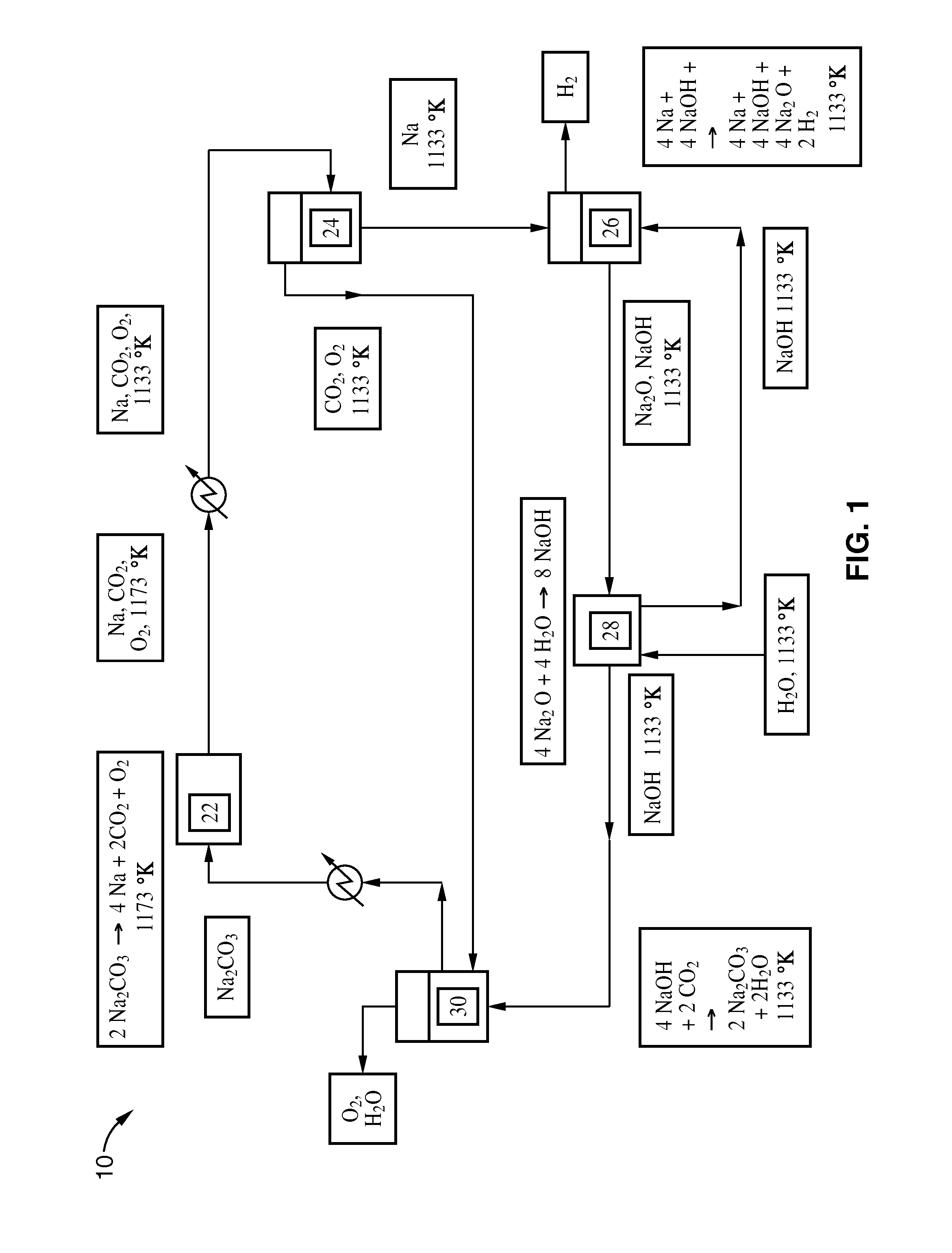
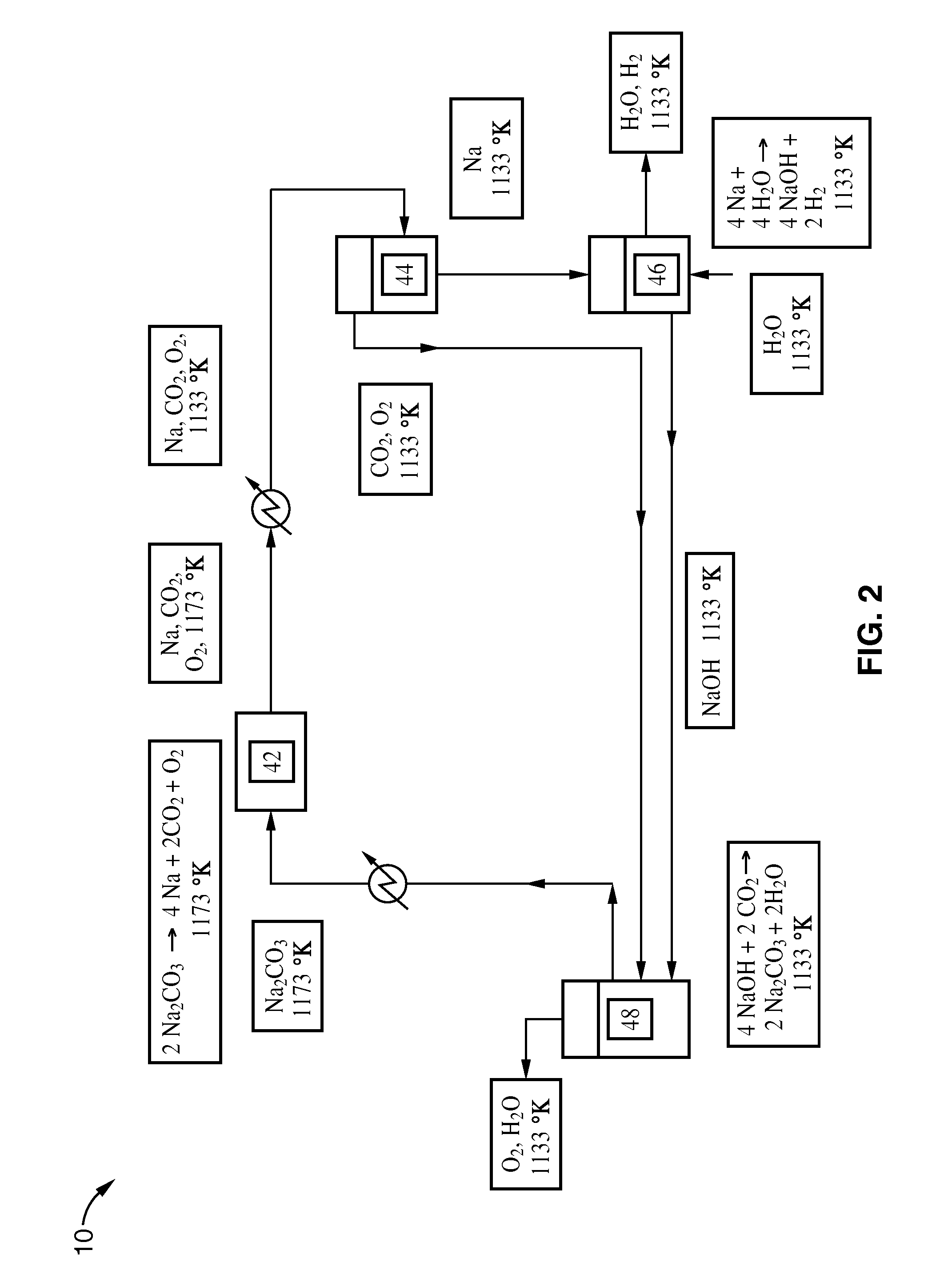
[0032]Another embodiment of the thermochemical cycle involves sodium, sodium carbonate, sodium hydroxide, and carbon dioxide as intermediates that help facilitate water decomposition. A process according to this embodiment is shown in FIG. 2.
2Na2CO3→4Na+2CO2+O2 (6)
4Na+4H2O→4NaOH+2H2 (7)
4NaOH+2CO2→2Na2CO3+2H2O (8)
[0033]The reactions can be carried out at a variety of temperatures. Reaction (6) is endothermic and can typically be carried out around 1173 K, where all its products are gases. Kinetic rate information at 1173 K is given in Hughes et al., “Production of the Boranes and Related Research”, Academic Press, New York, 1967. Reaction (7) is exothermic and can be carried out at room temperature or even around 1133 K. Care must be taken to control the rate of reaction (7). This can be accomplished by running the reaction with excess steam. Reaction (8) is also exothermic and can also be carried out around 1133 K. The choice of operating temperature for these reactions depends o...
example 3
[0036]A third embodiment is given by the system of equations:
2Na2CO3→4Na+2CO2+O2 (9)
4Na+4H2O→4NaOH+2H2 (10)
4NaOH+4CO2→4NaHCO3 (11)
4NaHCO3→2Na2CO3+2H2O+4CO2 (12)
[0037]Referring to FIG. 3, sodium carbonate is first placed in vessel 62 and heated. The sodium carbonate decomposes to a gaseous mixture of sodium, oxygen, and carbon dioxide. The gas mixture is then cooled to liquefy the sodium, and the mixture is sent to vessel 64, where separation takes place. The sodium is cooled and sent to vessel 66, where it reacts to completion with water to form sodium hydroxide and hydrogen. Although FIG. 3 shows the reaction in vessel 66 with liquid water, the reaction can take place with liquid water or with steam. Heat must be removed from vessel 66 to ensure stable operation. The sodium hydroxide and some water are then sent to vessel 68, where it is placed in contact with the oxygen and carbon dioxide from vessel 64. The carbon dioxide is adjusted so that the hydroxide reacts to completion...
PUM
| Property | Measurement | Unit |
|---|---|---|
| operating temperature | aaaaa | aaaaa |
| operating temperature | aaaaa | aaaaa |
| temperatures | aaaaa | aaaaa |
Abstract
Description
Claims
Application Information