
Tandem photochemical-thermochemical process for hydrocarbon production from carbon dioxide feedstock

a carbon dioxide feedstock and photochemical technology, applied in the field of thermochemical, photocatalytic processes and systems, can solve the problems of low yield, long way to be efficient and commercially viable devices for the scientific community, etc., and achieve the effect of energy efficien

Inactive Publication Date: 2016-11-24
BOARD OF RGT THE UNIV OF TEXAS SYST
View PDF5 Cites 6 Cited by
  • Summary
  • Abstract
  • Description
  • Claims
  • Application Information

AI Technical Summary

Benefits of technology

The patent describes a way to generate heavier hydrocarbons using sunlight and a photoactive material. This process is energy efficient and can produce energy from the sun's rays. The technology involves combining water photo-oxidation with CO or CO2 photo-reduction and thermal-chemical carbon-chain formation. Overall, this invention allows for effective use of solar energy for the production of valuable chemicals.

Problems solved by technology

Despite nearly 40 years of research on the photocatalytic reduction of CO2, the scientific community is still a long way from efficient and commercially viable devices.
Presently, yields are too low to be viable and predominantly produce methane.

Method used


Image

  • Tandem photochemical-thermochemical process for hydrocarbon production from carbon dioxide feedstock
  • Tandem photochemical-thermochemical process for hydrocarbon production from carbon dioxide feedstock
  • Tandem photochemical-thermochemical process for hydrocarbon production from carbon dioxide feedstock

Examples


example 1

Preparation of Titanium Dioxide / Cobalt Catalyst

[0072]Titanium dioxide-cobalt catalyst were prepared by incipient wetness impregnation of TiO2 (rutile) with sufficient aqueous solution of CoNO3 (Alfa Aesar) to give a loading of 5% by mass cobalt when dried, calcined, and reduced. The impregnated TiO2 was dried at room temperature for overnight and calcinations under air at 225° C. for 3 h and then sieved using No 100 (opening 0.15 mm). The dried catalyst was reduced at 400° C. in a flow of H2 for 8 h. XPS spectroscopy indicated that only 1% of the cobalt present was in the metallic state, the remainder was present as Co2O3.

example 2

Preparation of the Catalyst on a Substrate

[0073]The catalysis supports were Pyrex glass pellets having a 2 mm diameter. Before Co—TiO2 catalyst was immobilized on the Pyrex glass pellets, these glass pellets were etched in 5M NaOH solution for 24 h at 70° C. After they had been rinsed with DI water, the glass pellets were soaked in an aqueous suspension, which was prepared with 3 g of catalyst as prepared in Example 1 and dispersed in 3.0 mL of DI water with the aid of an ultrasonic bath to which 3.0 mL of 5% w / w Nafion PTFE was added. After removing from the Catalyst-PTFE solution, the glass pellets were heated at 70° C. in a vacuum oven. The resulting pellets were opaque with a dull gray powder thinly coated on the surface.

example 3

Preparation of Packed-Bed Thermophotocatalytic Reactor

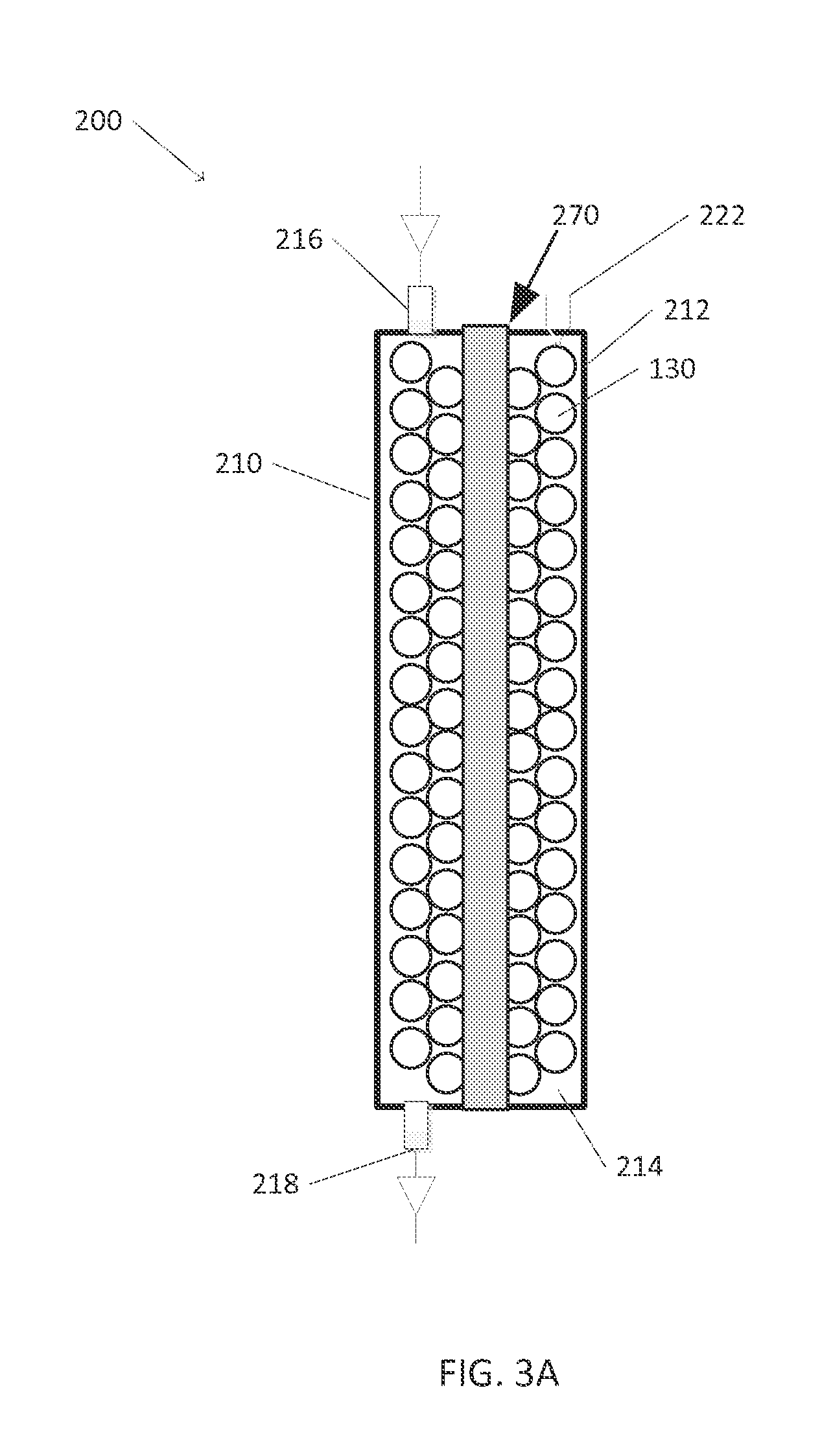
[0074]A quartz tube having a length of 10 in. and a diameter of 1.4375 in. and a wall thickness of ⅛ in. and two plastic caps that fit on each end of the tube comprised the catalytic chamber. A stainless steel tube with an inner diameter of 0.25 in. and a length of 10 in. was placed along the center of the center of the quartz tube, and a cartridge heater was placed inside the stainless steel tube. The quartz tube was filled with the catalytic pellets as prepared in Example 2. Three holes were drilled on one of the caps and one hole was drilled in the other. Graphite tape, metal camps, and high temperature PTFE O-rings were placed between the caps and the tube to provide the necessary seal. A thermocouple was inserted into one hole, the cartridge heater was inserted through a central hole, and a fitting for the inflow gas line was placed in the third. A fitting for the outflow gas line was placed in the hole of the other cap. The...


PUM

PropertyMeasurementUnit
temperatureaaaaaaaaaa
reaction temperatureaaaaaaaaaa

Abstract

The present invention is directed at an improved process for generating heavier hydrocarbons from carbon dioxide and / or carbon monoxide and water using tandem photochemical-thermochemical catalysis in a single reactor. Catalysts of the present disclosure can comprise photoactive material and deposits of conductive material interspersed on the surface thereof. The conductive material can comprise Fischer-Tropsch type catalysts.

Description

[0001]This application claims priority to U.S. Provisional Application No. 61 / 928,719 filed Jan. 17, 2014. The entire text the above-referenced disclosure is specifically incorporated herein by reference without disclaimer.BACKGROUND OF THE INVENTION[0002]A. Field of the Invention[0003]The invention generally concerns thermal, photocatalytic processes and systems that can be used to produce hydrocarbons from water and C1 feedstocks, e.g., CO and / or CO2.[0004]B. Description of Related Art[0005]Recycling CO2 to produce hydrocarbons, particularly long chain hydrocarbons, in a commercially viable manner has long been a goal of scientific research. Such a process could produce a chemical fuel and assist in curbing the effect of climate change.[0006]In order to achieve commercial viability, the energy required must be provided from a renewable source. One source that holds particular promise is the sun. Solar light energy provides a seemingly infinite source of energy. Thus, harvesting th...

Claims


Application Information

Patent Timeline
Patent Type & Authority Applications(United States)
IPC IPC(8): C10G2/00C07C41/01C07C29/159B01J23/75B01J35/00
CPCC10G2/40C10G2/00C07C41/01B01J35/004C07C29/159B01J23/75C07C27/04B01J8/065B01J8/067B01J10/007B01J19/127B01J19/1818B01J19/1825B01J8/006B01J2208/00044B01J2208/00398B01J2208/00451B01J2219/00038B01J2219/0004B01J2219/00058B01J2219/00132B01J2219/00144C10G2/33C10G2/332C10G2/35C10G2/50C10G2300/70B01J37/18B01J37/0219B01J21/063B01J37/0201B01J37/0217Y02P20/52Y02P20/141B01J35/391B01J35/30C07C31/04C07C31/10B01J35/39
Inventor MACDONNELL, FREDERICKDENNIS, BRIANCHANMANEE, WILAIWAN
Owner BOARD OF RGT THE UNIV OF TEXAS SYST
Learn More