
Optical disk apparatus

a technology of optical disk and optical disk, which is applied in the field of optical disk apparatus, can solve the problems of system using such a method, deterioration of signal to noise ratio (snr), and difficulty in separating the read signal in the baseband and the higher-order spectrum, so as to prevent snr deterioration, reduce laser noise, and increase read speed

Inactive Publication Date: 2011-06-28
HITACHI CONSUMER ELECTRONICS CORP
View PDF13 Cites 2 Cited by
  • Summary
  • Abstract
  • Description
  • Claims
  • Application Information

AI Technical Summary

Benefits of technology

"The present invention is an optical disk apparatus that improves read speed and prevents signal-to-noise ratio deterioration. It solves the difficulty in separating a read signal and HF signal components, reduces laser noise, and maintains high reliability during high-speed read operations. The apparatus includes a unit that converts a pulse read signal into a continuous signal, a unit that captures and holds the peak value of each pulse, a unit that reduces the emission-line spectrum, and a unit that eliminates laser noise. The invention also makes it easy to use high-frequency modulation to reduce laser noise while allowing a high-speed read operation."

Problems solved by technology

As the read speed is increased in the future, however, a system using such a method will encounter at least the following two problems.
First of the two problems is deterioration of the signal to noise ratio (SNR) on account of the read signal bandwidth expansion.
The second problem is that, as the read signal bandwidth expands, the HF frequency and the read signal bandwidth come closer to each other making it difficult to separate the read signal in the baseband and the higher-order spectrum.
The first problem arises when the read speed is increased regardless of the method used.
The second problem is peculiar to systems using high-frequency modulation.
Therefore, as the upper limit frequency of the read signal and the HF frequency come closer to each other, it becomes difficult to separate them.
Sence the HF frequency being a parameter determined to be optimum for laser noise elimination, simply increasing the HF frequency makes it less optimum for laser noise elimination, so that it cannot be arbitrarily changed.

Method used


Image

  • Optical disk apparatus
  • Optical disk apparatus
  • Optical disk apparatus

Examples


first embodiment

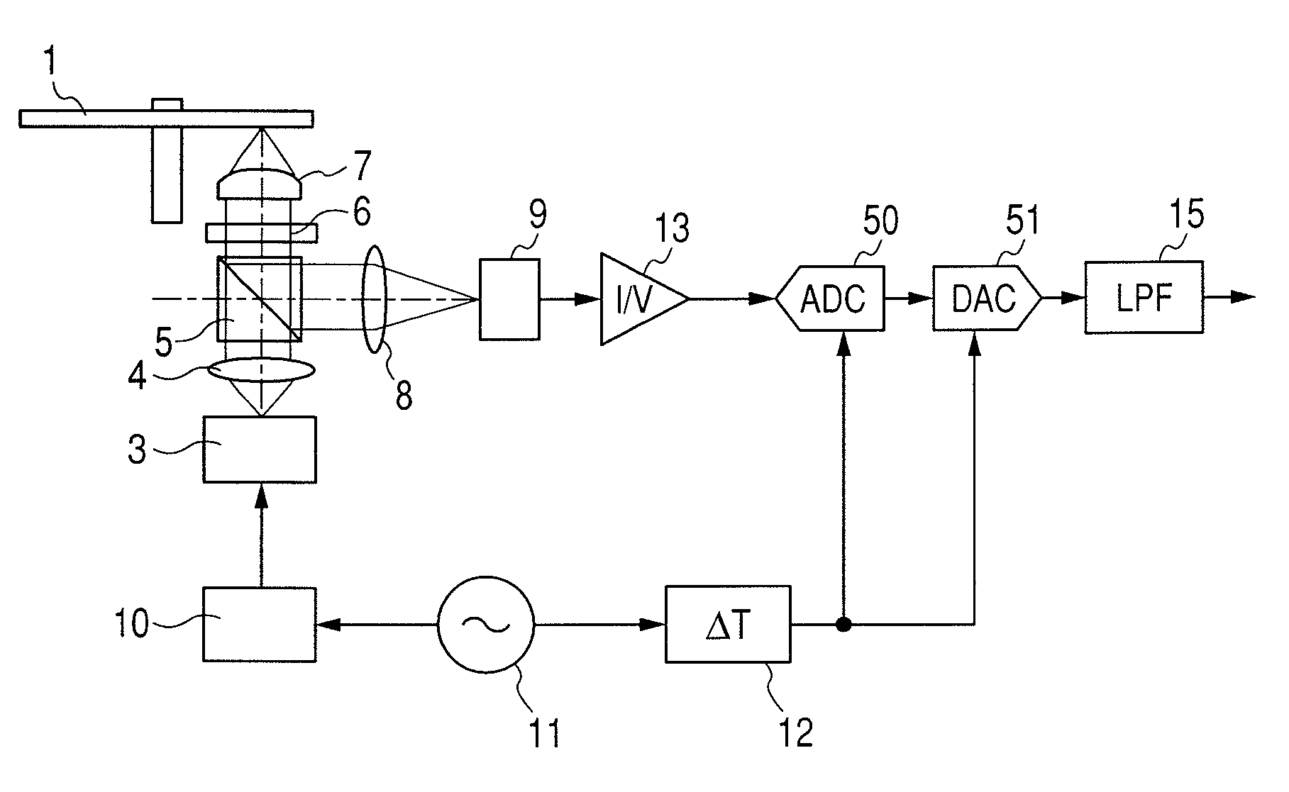
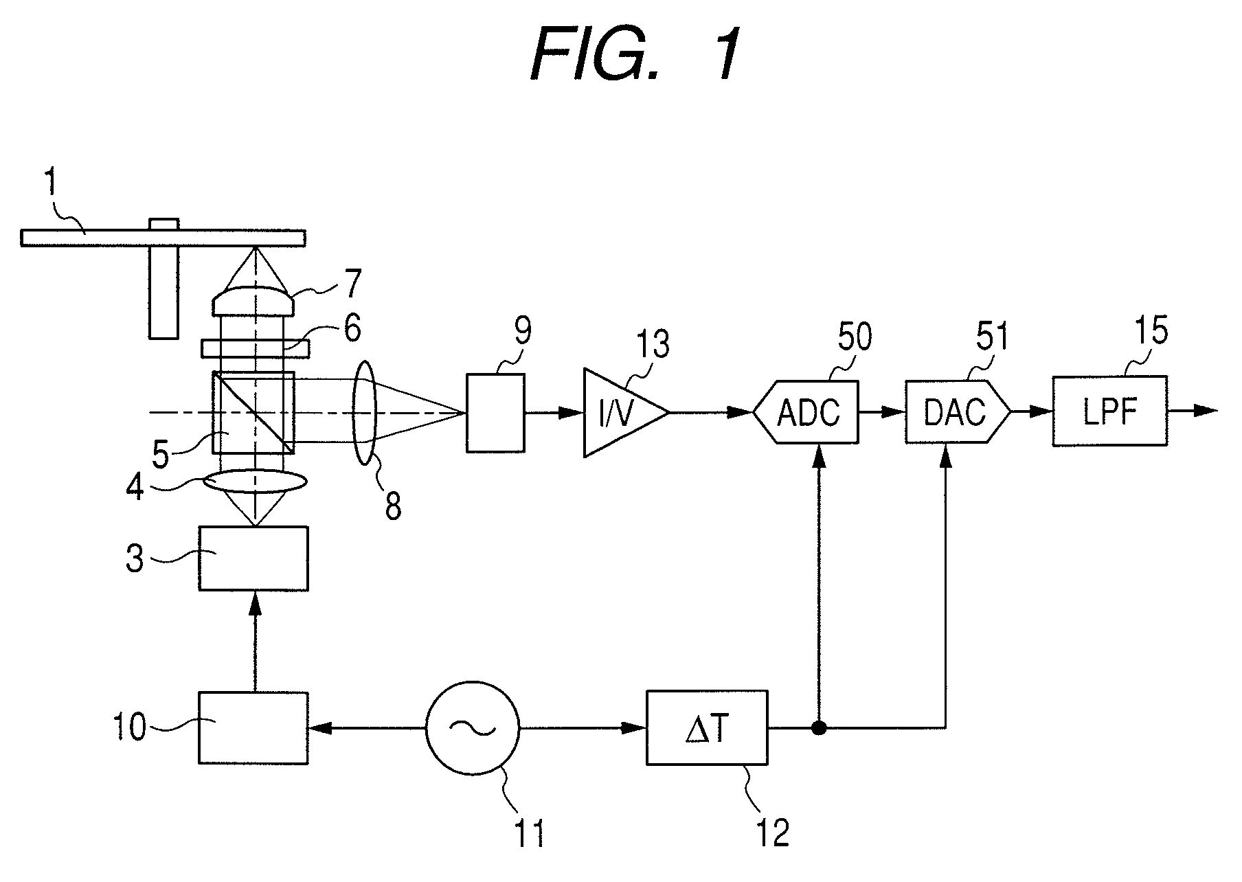
[0037]FIG. 1 is a schematic diagram showing an example of an optical disk apparatus according to the present invention. The schematic diagram mainly illustrates the pickup section of the optical disk apparatus with portions of the optical disk apparatus which are not indispensable for the following description omitted. The present embodiment is characterized in that it uses an analog to digital (AD) converter 50 and a digital to analog (DA) converter 51 to convert a pulse read signal into a continuous waveform signal. The pulse read signal is composed of a train of temporally discrete pulses. The essence of the pulse read signal is in the time of occurrence and the peak value of each pulse. The continuous signal referred to in the present specification refers to a signal which differs from the pulse read signal in that it is not composed of essentially temporally discrete components (pulses) only. The continuous signal as referred to in this specification, therefore, has a broader s...

second embodiment

[0046]FIG. 8 is a schematic configuration diagram of an optical disk apparatus in which laser noise is reduced according to the present invention. The second embodiment is characterized in that: a laser power monitor having a wide bandwidth comparable to the one used in the first embodiment is used; the amplitude of power monitor output is measured using an AD converter; and the measurement result is used to eliminate laser noise.

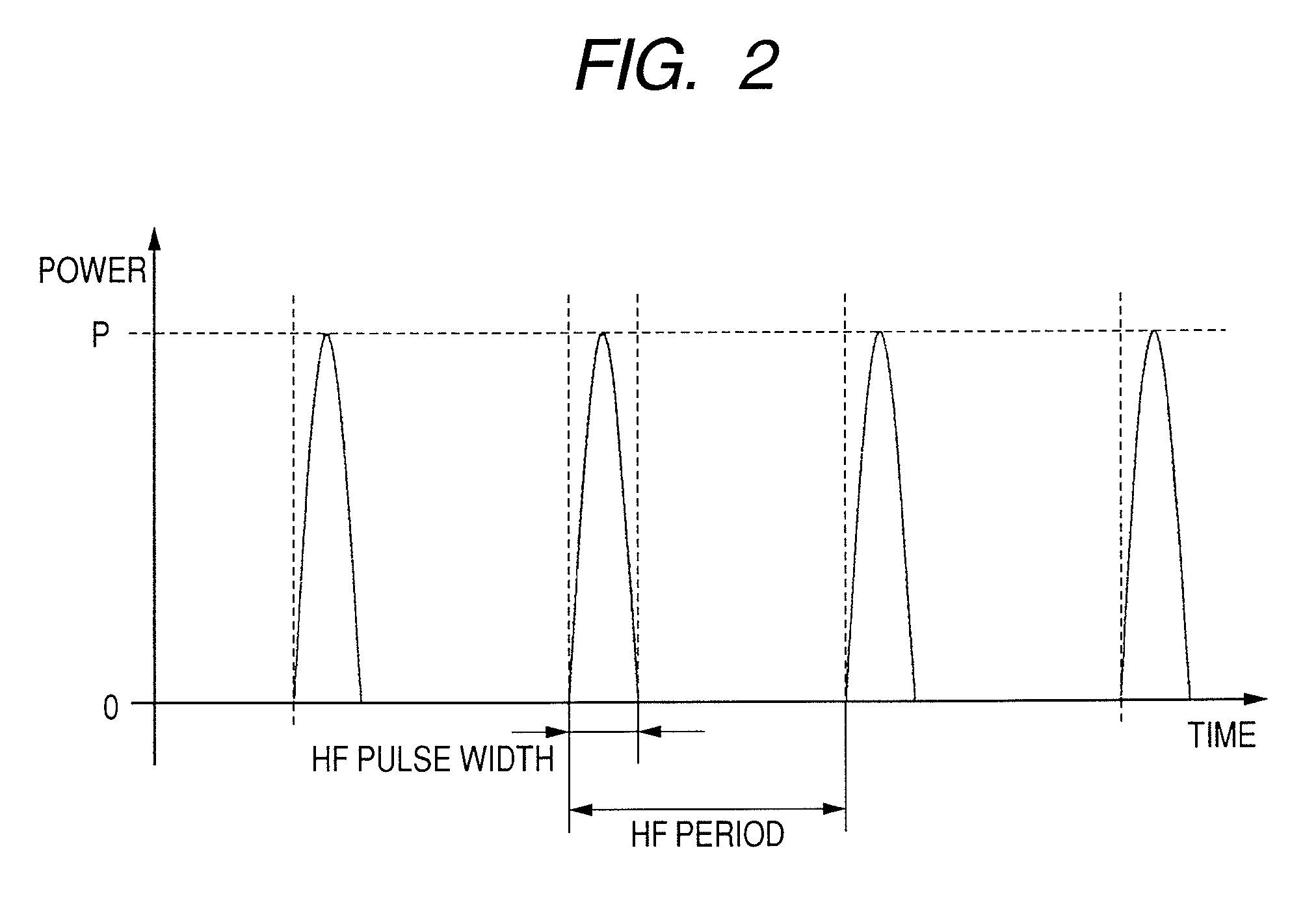
[0047]A high-frequency (HF) signal to be superimposed is generated at an HF oscillator 11 and inputted to a laser driver 10. The laser driver generates a laser drive current required to obtain a desired average laser power, peak power, and duty, and inputs the laser drive current to a laser diode 3. The laser driver also controls the laser drive current so as to keep the average laser power constant. At this time, the laser diode is pulsed as shown in FIG. 2.

[0048]The laser beam is collimated by a collimator lens 4. Part of the collimated laser beam is, at ...

third embodiment

[0055]When part of a laser beam is branched to the power monitor system, the ratio of the laser beam portion reaching the disk decreases. This does not pose any problem for a read-only apparatus. In the case of a recordable optical disk apparatus, however, it is necessary to secure certain amount of light usable for recording, so that the ratio of the laser beam portion that may be branched to the power monitor system is limited. At the same time, if the laser beam portion branched to the power monitor system is less than required, the SNR (signal to noise ratio) of the signal processed in the power monitor system decreases, for example, on account of amplifier noise and such. This lowers the laser noise elimination accuracy.

[0056]One method of avoiding this problem is to change the division ratio of the beam splitter depending on occasions: recording or reading. Such a method can be realized by using a liquid crystal device. Because liquid crystal devices are slow-response devices,...


PUM

PropertyMeasurementUnit
HF frequencyaaaaaaaaaa
frequencyaaaaaaaaaa
HF frequencyaaaaaaaaaa

Abstract

An optical disk apparatus is provided which can: prevent an SNR deterioration attributable to an increase in read speed; overcome difficulty in separating a read signal and HF signal components; reduce laser noise; and maintain high reliability even during a high-speed read operation. An optical disk is irradiated with laser light pulsed by a high-frequency signal generated by a HF oscillator. The output of an optical detector which receives laser light reflected from the optical disk is converted into an electric pulse read signal using a current amplifier. The pulse read signal is converted into a temporally continuous read signal using a combination of an AD converter and a DA converter.

Description

CLAIM OF PRIORITY[0001]The present application claims priority from Japanese application JP 2007-055011 filed on Mar. 6, 2007, the content of which is hereby incorporated by reference into this application.FIELD OF THE INVENTION[0002]The present invention relates to an optical disk apparatus and more particularly to a circuit for reading information from an optical disk.BACKGROUND OF THE INVENTION[0003]Many of the optical disk apparatuses, including DVD drives, currently in use employ a high-frequency modulation method to reduce noise generated by a laser diode used as a laser light source. This is commonly known among those in the art. In terms of the high-frequency modulation method, therefore, only aspects associated with the present specification will be described in the following only to a required extent without further elaboration.[0004]The background of the invention will be described below with reference to the inventions disclosed in JP-A No. H8 (1996)-77640, JP-A No. H8 (...

Claims


Application Information

Patent Timeline
Patent Type & Authority Patents(United States)
IPC IPC(8): G11B7/00
CPCG11B7/126G11B7/005
Inventor KIKUGAWA, ATSUSHI
Owner HITACHI CONSUMER ELECTRONICS CORP
Learn More