Sensor magnet holder for use in motor and its manufacturing process

a technology for sensor magnets and manufacturing processes, applied in the direction of manufacturing tools, mechanical energy handling, instruments, etc., can solve the problems of insufficient torque in the prior art, complex structure of prior art rotation detection devices, complex structural forms of devices, etc., to achieve strong press, improve moving resistance, and the effect of hard damage to the magn

Active Publication Date: 2011-07-05
MABUCHI MOTOR
View PDF6 Cites 6 Cited by
  • Summary
  • Abstract
  • Description
  • Claims
  • Application Information

AI Technical Summary

Benefits of technology

[0014]The current invention is to fix the sensor magnet holder on the motor shaft not by applied force on the sensor magnet but by press fitting via the press fit portions of the sensor magnet holder which fixedly positions a magnet. The current invention enables sufficient strong press fit while it makes harder to damage the magnet. By the above press fit, the shaft and the sensor magnet holder improve moving resistance. Furthermore, the rectangular inner surfaces of the sensor magnet improve anti-rotational torque of the sensor magnet.
[0015]The current invention lacks some additional process such as the knurl process or a positional groove on the motor shaft so as to eliminate a cause of bending the shaft. The current invention enables a low-cost solution for fixing the sensor magnet both in the axial and rotational directions. The sensor magnet and the sensor magnet holder are engaged by press fit, and the sensor magnet does not become free after inserting onto a shaft.
[0016]The current invention is to prevent lubricating grease of the worm gear from flowing over a Hall effect sensor.
[0017]According to the current invention, since the snap fit board portions snuggly contacts the inner flat surface of the sensor magnet due to the flexibility, the sensor magnet and the sensor magnet holder lack a concave portion and a convex portion along the axial direction for an anti-rotational purpose. Consequently, a manufacturing process improves its operability. These and various other advantages and features of novelty which characterize the invention are pointed out with particularity in the claims annexed hereto and forming a part hereof. However, for a better understanding of the invention, its advantages, and the objects obtained by its use, reference should be made to the drawings which form a further part hereof, and to the accompanying descriptive matter, in which there is illustrated and described a preferred embodiment of the invention.

Problems solved by technology

The illustrated prior art rotation detection device has complex structural forms for determining the sensor magnet position and fixing the sensor magnet with respect to the magnet holder.
By the same token, the prior art rotation detection device also has complex structural forms for determining the magnet holder position and fixing the magnet holder with respect to the motor shaft.
Furthermore, the torque is not sufficiently large in the prior art for preventing the sensor magnet from rotating in the circumferential direction.
However, if the rotation detection device is placed near a worm gear, lubricating grease of the worm gear may flow over a Hall effect sensor.

Method used


Image

  • Sensor magnet holder for use in motor and its manufacturing process
  • Sensor magnet holder for use in motor and its manufacturing process
  • Sensor magnet holder for use in motor and its manufacturing process

Examples


Embodiment Construction

)

[0030]Based upon incorporation by external reference, the current application incorporates all disclosures in the corresponding Japanese priority document (2008-175240 filed on Jul. 4, 2008) from which the current application claims priority. The current invention involving a sensor magnet positioned and fixed on the shaft is applicable to all prior art small motors such as brushless motors and motors with a worm-gear speed reduction device whose rotational speed and angular position need to be detected. In the following, embodiments according to the current invention will be described with respect to exemplary motors with a worm-gear speed reduction device.

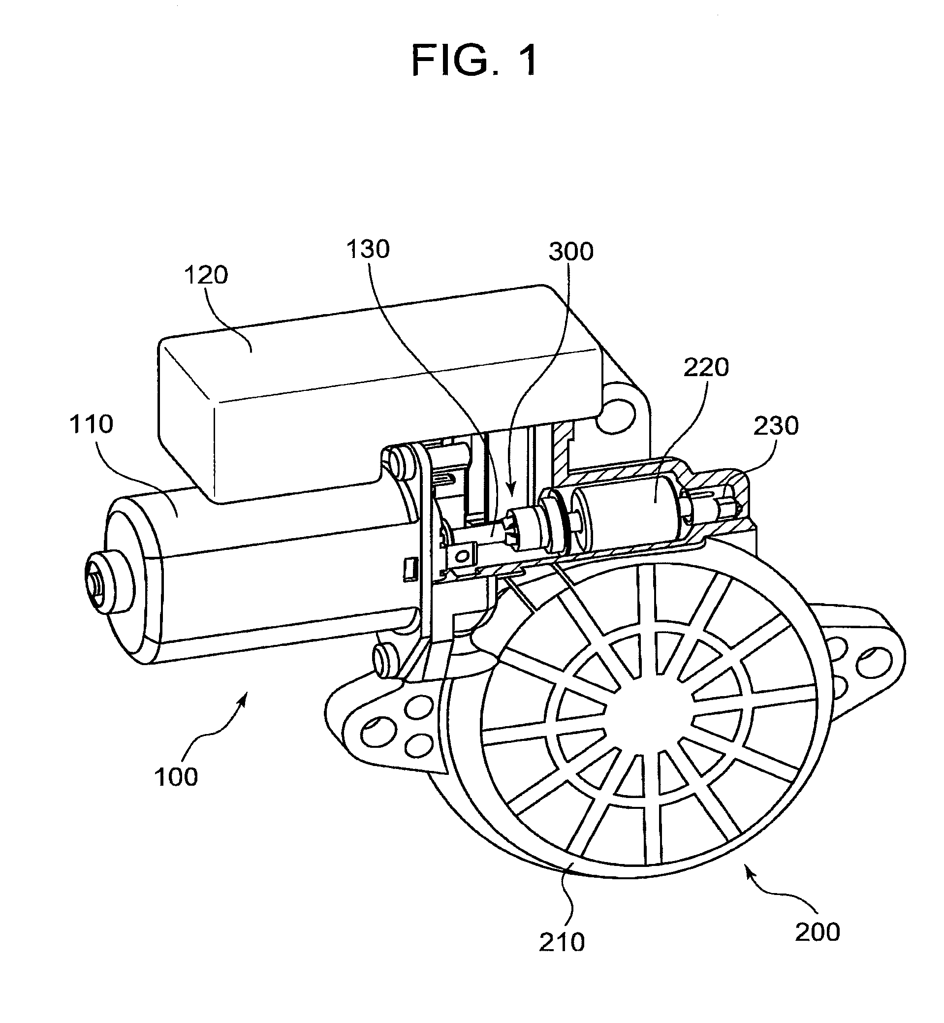
[0031]Referring now to the drawings, wherein like reference numerals designate corresponding structures throughout the views, and referring in particular to FIG. 1, a prospective view with a partial cross sectional surface illustrates an overall structure of a motor with a worm-gear speed reduction device including a rotation de...


PUM

PropertyMeasurementUnit
flexibilityaaaaaaaaaa
internal diameteraaaaaaaaaa
inner diameteraaaaaaaaaa

Abstract

A sensor magnet holder is mounted on a motor shaft, and a sensor magnet is provided relative to a magnetic induction sensor on the non-moving side for obtaining a signal indicative of a rotational position of the motor shaft. The sensor magnet holder integrally forms a cylindrical portion, a flange portion of a terminal end of the cylindrical portion having a large diameter, a magnet rear end holding portion of the other terminal end of the cylindrical portion and a plurality of snap fit board portions. A shaft press fit portion is formed on an internal diameter of the flange portion. The plural snap fit board portions extend from the cylindrical portion in an axial direction of the motor shaft. A magnet front end holding portion is formed at an extending tip over an outer diameter surface of each of the snap fit board portions. Each of the flexible snap fit board portions snuggly contacts the inner flat surface of the sensor magnet while the sensor magnet is held between said magnet rear end holding portion and said magnet front end holding portion.

Description

FIELD OF THE INVENTION[0001]The current invention is generally related to a holder for housing sensor magnets and a motor incorporating the same holder and more particularly related to the sensor magnet device that generates a signal indicative of the rotor angular position by detecting a magnetic position in response to the motor shaft rotation. The current invention is related to the above-described holder, the motor incorporating the same holder and their manufacturing process.BACKGROUND OF THE INVENTION[0002]In a small motor, a rotation detection device for detecting a rotational speed or position has been integrated into a motor rational component such as a motor shaft. For example, these rotation detection devices have been used to gain the angular positional information in brushless motors. As already known in prior art, in the brushless motor, a magnet known as a sensor magnet is installed on the rotational shaft while a magnetic induction sensor is placed near the sensor ma...

Claims


Application Information

Patent Timeline
Patent Type & Authority Patents(United States)
IPC IPC(8): G01B7/30
CPCH02K11/0021H02K23/66H02K7/1166Y10T29/5313Y10T29/49002H02K11/215
Inventor KIKUCHI, SATOSHIAKIMOTO, TAKAHIRO
Owner MABUCHI MOTOR
Why Eureka
Try Eureka