
Apparatus and method for organizing cables in a cabinet

a technology of cables and cabinets, applied in the field of equipment cabinets, can solve the problems of large volume of cables, complex joining lengths of optical fibers, and difficulty in routing and otherwise managing cables, so as to improve the routing of fiber trunk cables, improve optical fiber organization, and reduce fiber congestion

Active Publication Date: 2011-07-05
CHATSWORTH PROD INC
View PDF277 Cites 141 Cited by
  • Summary
  • Abstract
  • Description
  • Claims
  • Application Information

AI Technical Summary

Benefits of technology

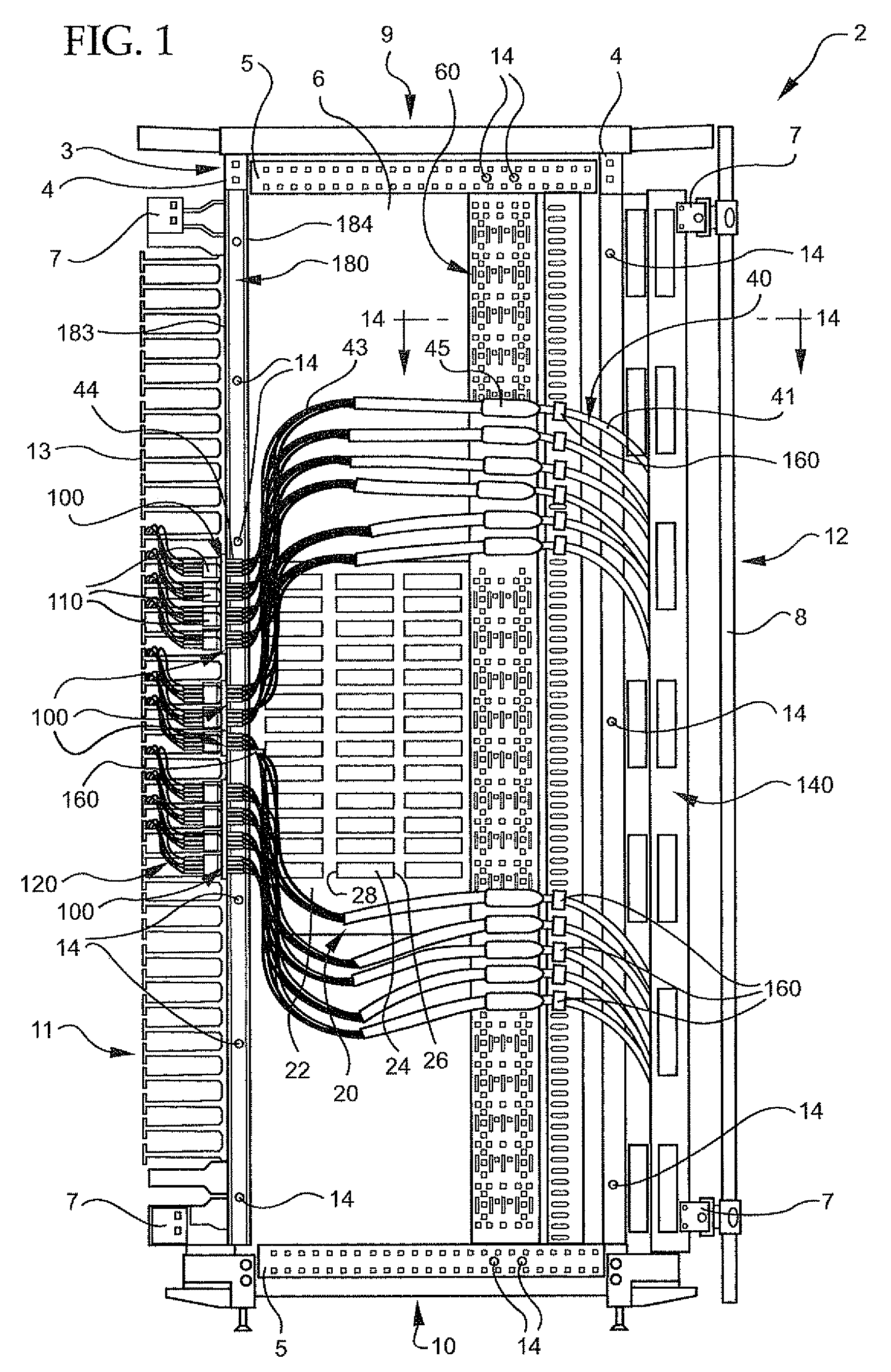
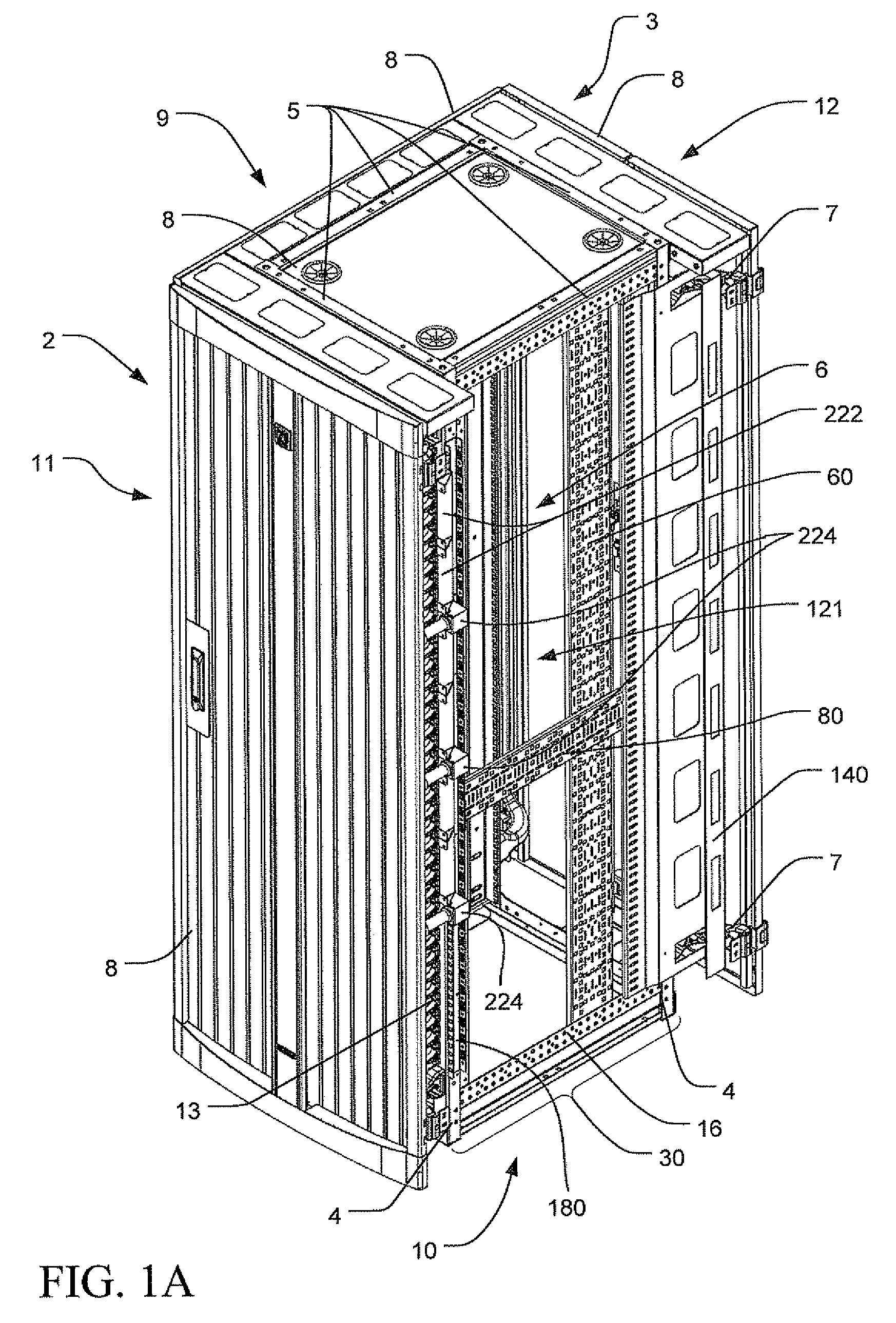
The patent text describes an equipment cabinet with a central rack space for mounting equipment. The cabinet includes organizational elements for mounting cables within the cabinet. These elements include a trunk cable with a furcation plug and a furcation bracket, a termination panel with sockets for connecting to the cables, and a trunk cable manager with two planar portions for supporting the cables. The trunk cable manager may also include a universal clip for mounting the furcation plug. The technical effects of this invention include reducing airflow obstacles and network degradation, facilitating moves, adds, or changes of equipment, and avoiding unwanted bending of cables.

Problems solved by technology

A particular problem inherent in the use of enclosures of all kinds is the issue of how to route and otherwise manage the large quantities of cables that are often necessary for a particular enclosure.
Optical fibers sometimes have unique problems associated with routing and managing the large quantity thereof in enclosures.
Because of the way in which optical fiber transmits data, joining lengths of optical fiber is more complex than joining electrical wire or cable.
Unfortunately, one of the fundamental challenges for high density storage area networks is the large volume of optical fiber cable and patch cords that must be managed in cabinets which house large, modular (core) switches, or other equipment.
It is readily apparent that such fiber volume concentrated along the sides of the cabinets can quickly become congested and disorganized causing problems with enclosure thermal management, blocking airflow, increasing risk of unwanted bending of the cables, and making it difficult to administer networking moves, adds and changes.
Further, this congestion reduces accessibility to the equipment, creates a mass of cable that is difficult to work with, and increases the cost of implementing routine changes to the network.
This solution consumes valuable rack-mount space within the enclosure that could be used to house electronic equipment.
Further, housing fiber connectors in the rack-mount space increases optical fiber congestion by requiring the optical fibers to enter back into the rack-mount space after the have exited such space when leaving the core switches, i.e., typically optical fiber is routed away from a core switch in the rack-mount space into side panel space of an enclosure and then routed back to a fiber connector in the rack-mount space.
However, currently available connectors that may be mounted in the side space are restricted to fixed locations and low capacities by the limitations of the fixed brackets that are currently available.
By providing the organizational elements in a kit, the user is guaranteed that the organizational elements will assemble and work together without attempting to cross-reference component specification sheets or have to field trial compatibility, which takes considerable time and money.

Method used


Image

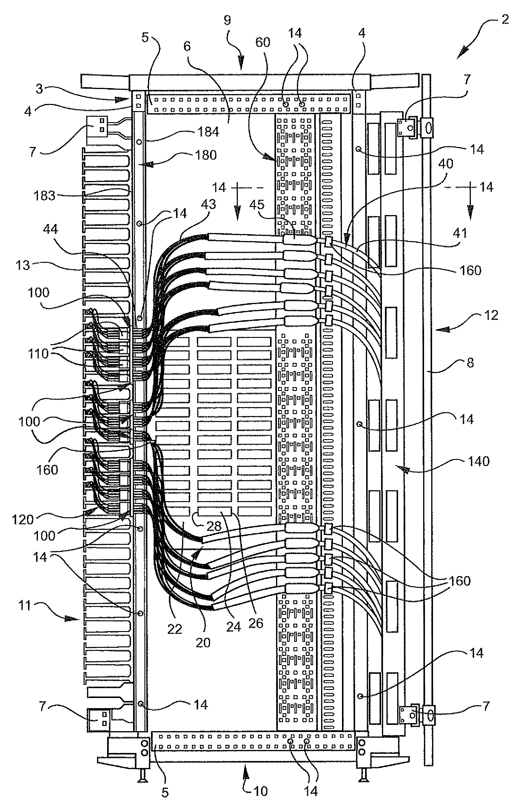
  • Apparatus and method for organizing cables in a cabinet
  • Apparatus and method for organizing cables in a cabinet
  • Apparatus and method for organizing cables in a cabinet

Examples


Embodiment Construction

[0092]As a preliminary matter, it will readily be understood by one having ordinary skill in the relevant art (“Ordinary Artisan”) that the present invention has broad utility and application. Furthermore, any embodiment discussed and identified as being “preferred” is considered to be part of a best mode contemplated for carrying out the present invention. Other embodiments also may be discussed for additional illustrative purposes in providing a full and enabling disclosure of the present invention. Moreover, many embodiments, such as adaptations, variations, modifications, and equivalent arrangements, will be implicitly disclosed by the embodiments described herein and fall within the scope of the present invention.

[0093]Accordingly, while the present invention is described herein in detail in relation to one or more embodiments, it is to be understood that this disclosure is illustrative and exemplary of the present invention, and is made merely for the purposes of providing a f...


PUM


Abstract

An equipment cabinet (2) includes an equipment rack (3) for mounting equipment (20), and includes organizational elements for organizing cables within the cabinet. The cables may be organized to reduce impeding airflow to or from the equipment, and / or to reduce unwanted bending of the cables themselves. The organizational elements may include one or more of: a trunk cable (40) including a furcation plug (45) and universal clip (47); a furcation bracket—either vertical (60) or horizontal (80); a termination panel (100); a trunk cable manager (140, 200); and / or an accessory bracket (180). The organizational elements may be used in various combinations with one another, and may be provided in a kit.

Description

CROSS-REFERENCE TO RELATED APPLICATIONS[0001]The present application is a U.S. nonprovisional patent application of, and claims priority under 35 U.S.C. §119(e) to, each of:[0002](1) U.S. provisional patent application Ser. No. 61 / 019,596, filed Jan. 7, 2008;[0003](2) U.S. provisional patent application Ser. No. 61 / 019,592, filed Jan. 7, 2008;[0004](3) U.S. provisional patent application Se. No. 61 / 010,807, filed Jan. 11, 2008; and[0005](4) U.S. provisional patent application Ser. No. 61 / 020,741, filed Jan. 13, 2008.Each of the foregoing provisional patent applications is incorporated by reference herein.COPYRIGHT STATEMENT[0006]All of the material in this patent document is subject to copyright protection under the copyright laws of the United States and of other countries. The copyright owner has no objection to the facsimile reproduction by anyone of the patent document or the patent disclosure, as it appears in the Patent and Trademark Office patent file or records, but otherwis...

Claims


Application Information

Patent Timeline
Patent Type & Authority Patents(United States)
IPC IPC(8): H02B1/01
CPCG02B6/4459H04Q1/062G02B6/4452G02B6/44524G02B6/44526G02B6/44528
Inventor DEAN, JR., DAVID LEEDONOWHO, DAVID BRIANLEWIS, II, RICHARD EVANSMESSMER, KARL THEODOREUGOLINI, ALAN WILLIAM
Owner CHATSWORTH PROD INC
Learn More