Apparatus and method of automated manufacturing

a technology of automatic manufacturing and manufacturing apparatus, applied in the direction of instrumentation, electric programme control, program control, etc., can solve the problems of increasing output, reducing rework, and not providing direction for possible modifications or improvements for the next iteration

Inactive Publication Date: 2011-07-05
GM GLOBAL TECH OPERATIONS LLC
View PDF35 Cites 20 Cited by
  • Summary
  • Abstract
  • Description
  • Claims
  • Application Information

AI Technical Summary

Benefits of technology

[0012]The present invention provides improved methods of optimizing collision free path planning for automated manufacturing and automated robotic welding processes. The methods presented herein are operable to create and edit an intelligent road map and weld gun selection sequence based upon complex geometric shapes. The methods are also developed for assembly process verification that enable generation and editing of weld gun paths and sequences in a managed, 3-dimensional (3D) environment. The methods described herein allow for the systematic determination of optimal weld gun orientations and robotic paths, and automatically plan a collision free path from the initial, home configuration to the weld point, goal configuration.
[0013]The present invention provides for faster positioning and more precise, optimized weld gun orientations and home and weld point configurations, thereby improving work plan cycle times, increasing the efficiency of individual robot cells, and reducing or eliminating re-work by downstream activities (e.g., robot programming and control). In addition, reduced joint motion and component stress translates into realized extended robot life. Finally, the methods described herein allow for complete elimination of human intervention, negating associated labor costs, such as, but not limited to, engineering services typically contracted for in each vehicle program.

Problems solved by technology

Accordingly, automated robotic welding results in relatively less scrap materials, decreased rework, and increased output.
While the simulation tools help in the computation of the results at each iteration, they do not provide direction for possible modifications or improvements to be made for the next iteration.
An ill-placed or improperly programmed robot risks inefficient operation and even failure.
While PRMs and other similar path planners produce geometrically feasible solutions, the solutions may not meet other manufacturing criteria.
For example, the path calculated, if one is found at all, may involve joint motions that are generally unacceptable for implementation on a manufacturing plant floor (e.g., excessive joint motion or stress on attached cables).
The resulting path will generally satisfy any geometric constraints, but may fail to meet other manufacturing parameters, often requiring significant modification later in the process.
Consequently, prior practice is to manually test various orientations in an iterative and time consuming process.
However, automated solutions of the prior art do not systematically determine and jointly optimize all system design variables—e.g., the home position Qh for the robot, the orientations of the weld gun at the goal configuration Qg—e.g., weld point, and a collision free path 12 that visits a given sequence of weld locations.

Method used


Image

  • Apparatus and method of automated manufacturing
  • Apparatus and method of automated manufacturing
  • Apparatus and method of automated manufacturing

Examples


Embodiment Construction

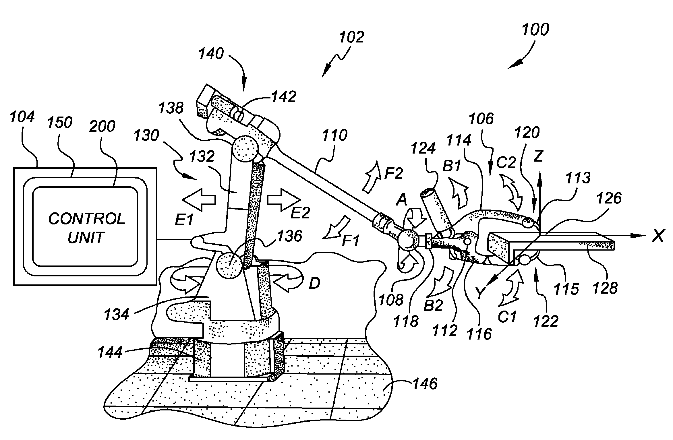
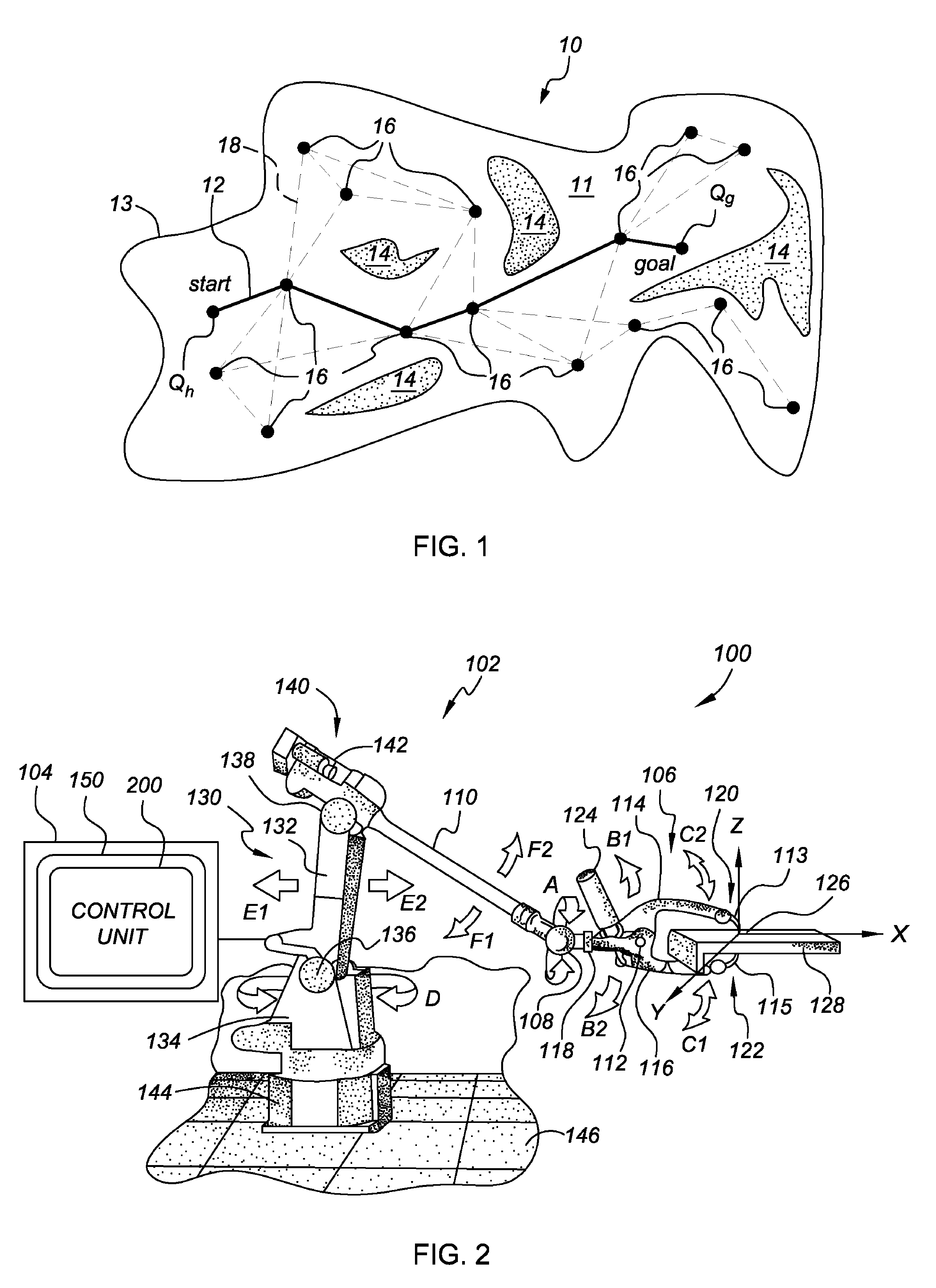
[0026]Referring to the figures, wherein like reference numbers refer to like components throughout the several views, there is shown an exemplary automated robotic welding cell or system, partially illustrated and identified generally in FIG. 2 as element 100. The present invention will be described herein with respect to the robotic welding cell 100 of FIG. 2 as an exemplary application by which the present invention may be incorporated and practiced. However, the present invention by no means is intended to be limited to the particular configuration or structure of FIG. 2. To that extent, the present invention can be used in a variety of automated manufacturing processes. By way of example, the apparatus and method provided herein can be employed for operating in a variety of welding processes, including single workpiece operations, joining two or more workpieces together, or for joining two ends of a single workpiece together, as well as non-welding based automated manufacturing ...


PUM


Abstract

An apparatus and method of optimizing collision free path planning comprising: initializing a plurality of feasible configuration points, sample points located in a free space, and sample points not located in the free space; determining a goodness rating of the various pluralities of points; generating new candidate points; determining if each new candidate point is a feasible configuration point and adding each to the plurality of feasible configuration points if it is; if not, determining if each new candidate point is located in the free space and adding it to the plurality of sample points located in the free space if it is; if not, adding to the plurality of sample points not located in the free space; determining an updated goodness rating of the various pluralities of points; determining if a termination criteria has been met and reporting a best solution or no solution if it has been met.

Description

CROSS-REFERENCE TO RELATED APPLICATIONS[0001]This application claims priority to U.S. Provisional Patent Application No. 60 / 863,612, filed on Oct. 31, 2006, which is hereby incorporated by reference in its entirety.TECHNICAL FIELD[0002]The present invention relates generally to automated manufacture and assembly process planning, and more specifically to systems and methods of automated robotic welding for determining optimal weld gun orientations and robot path planning.BACKGROUND OF THE INVENTION[0003]Robots are mechanized programmable tools used widely in automated manufacturing processes. Robots are generally employed to perform repetitive tasks in a precise and time efficient manner. In a typical manufacturing process, a robot performs a repetitive sequence of point-to-point movements, coming to a stop at each point to perform a task.[0004]Robots are utilized extensively in automobile production lines, for example, to apply spot welds to automobile frames at predetermined, prog...

Claims


Application Information

Patent Timeline
Patent Type & Authority Patents(United States)
IPC IPC(8): G05B19/19
CPCB25J9/1666G05B2219/40438G05B2219/40473Y02P80/40
Inventor TILOVE, ROBERT BRUCEBANDYOPADHYAY, SANDIPAN
Owner GM GLOBAL TECH OPERATIONS LLC
Why Eureka
Try Eureka