Multipole permanent-magnet synchronous machine having tooth-wound coils

a permanent magnet, multi-pole technology, applied in the direction of horology, magnetism circuit shape/form/construction, instruments, etc., can solve the problem of not knowing the optimum embodiment which satisfies, and achieves high copper fill factor, cost-increasing threading technique, and simple manufacturing

Inactive Publication Date: 2011-07-12
SIEMENS AG
View PDF36 Cites 13 Cited by
  • Summary
  • Abstract
  • Description
  • Claims
  • Application Information

AI Technical Summary

Benefits of technology

[0009]Furthermore, the tooth-wound coils may be in the form of prefabricated former-wound coils. This considerably simplifies manufacture. This variant manages without the teeth being wound on the stator laminate stack, which may otherwise involve a complex and therefore cost-increasing threading technique. The use of former-wound coils also results in a very high copper fill factor based on the slot cross section, as a result of which the nonreactive coil resistance is reduced and the capacity increases.
[0010]Another embodiment is characterized by the fact that the tooth-wound coils each comprise a winding comprising a plurality of turns, and the respective windings are designed such that adjacent turns are at slightly differing electrical potentials than one another during operation. In particular, the potential difference between adjacent turns is only a fraction of the electrical potential present between the two incoming coil lines. Thus, primarily also the first turn, which is connected to one incoming line, is therefore arranged within the winding such that it is locally separated from the last turn, which is connected to the other incoming line. As a result, the outlay on electrical insulation for the electrical conductors used for producing the tooth-wound coils can be reduced and a higher proportion of copper can be introduced into the slots. Precise positioning of the individual turns can be achieved particularly effectively by means of former-wound coils being prefabricated.
[0011]Preferably, the slots each have a side which faces the rotor and is designed to be open, with the result that the tooth-wound coils, which are in particular in the form of prefabricated former-wound coils, can be inserted easily. Also, the open slots bring about an advantageous inductance behavior with regard to sensorless operation.
[0012]Furthermore, it is advantageous if the slots have in each case two side walls, which extend away from the rotor and are arranged parallel to one another. In comparison with radially running side walls, the parallel embodiment is better suited for the use of prefabricated former-wound coils and also makes a higher copper fill factor possible.

Problems solved by technology

Despite the many available variants, as yet no optimum embodiment is known which satisfies these requirements equally.

Method used


Image

  • Multipole permanent-magnet synchronous machine having tooth-wound coils
  • Multipole permanent-magnet synchronous machine having tooth-wound coils
  • Multipole permanent-magnet synchronous machine having tooth-wound coils

Examples


Embodiment Construction

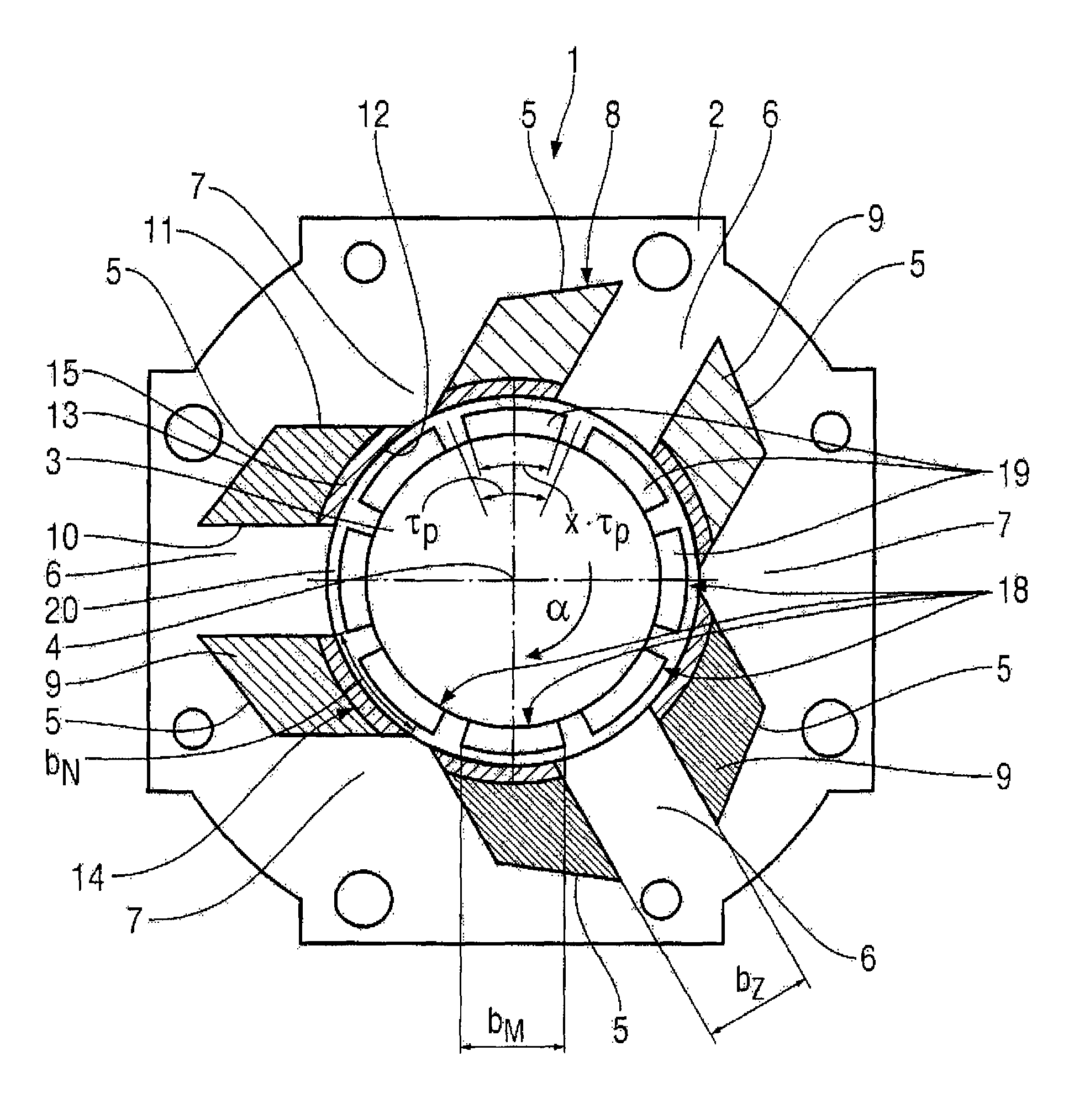
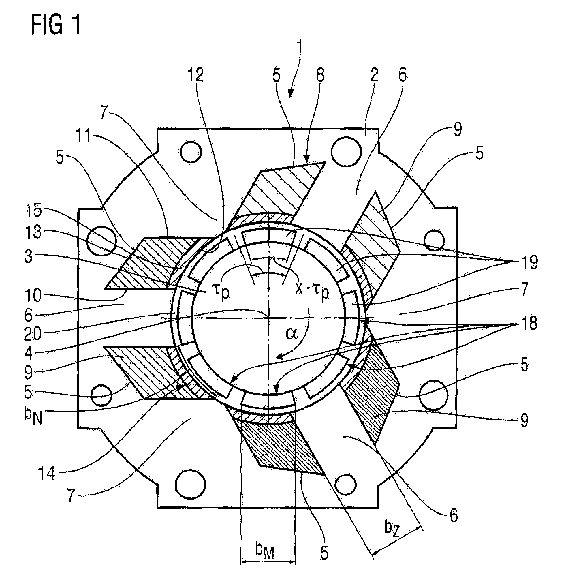
[0021]Mutually corresponding parts have been provided with the same reference symbols in FIGS. 1 and 2.

[0022]FIG. 1 shows a cross-sectional illustration of a permanent-magnet synchronous machine 1 in the form of a motor. It contains a stator 2 having a cylindrical stator bore and a rotor 3, which is arranged in the stator bore and is mounted such that it can rotate about an axis of rotation 4. The rotor 3 is an internal rotor. The stator 2 has six slots 5 on its inner wall facing the rotor 3, between which slots in each case teeth 6 and 7 are formed. A yoke around the outside connects the teeth 6 and 7 to one another. A winding system 8 having three winding phases and having in total three tooth-wound coils 9 is arranged in the slots 5, each of which tooth-wound coils being shown by different hatching in FIG. 1.

[0023]Each of the tooth-wound coils 9 surrounds one of the teeth 6, with the result that a wound tooth 6 alternates with an unwound tooth 7 in the circumferential direction. ...


PUM


Abstract

The permanently excited synchronous machine (1) includes a rotor (3) and a stand (2) which contains a three-branched winding system (8) which comprises tooth coils. The stand (2) has a total of three or six grooves (5) and a tooth (6, 7) is formed there between. A total of three tooth coils (9) are arranged in the grooves (5) and each coil is associated with one of the three winding phases. The number of user pole pairs (pN) is four or five. The rotor (3) has twice as many user pole pairs (pN) of permanent magnets (18) which are evenly distributed on the periphery.

Description

BACKGROUND OF THE INVENTION[0001]The invention relates to a permanent-magnet synchronous machine having a rotor and having a stator, which contains a winding system having three winding phases and being constructed with tooth-wound coils.[0002]Such a permanent-magnet synchronous machine is currently used in various embodiments. Examples are described in DE 199 61 760 A1 and in DE 101 24415A1. A current machine type involves a low coil number, for example three, always with a low useful pole pair number, for example of one. Such machines are operated with the basic pole pair number of the stator. Also known are so-called harmonic machines, in which a pole pair number of the rotor corresponds to an integral multiple of the basic pole pair number of the stator. Such multipole synchronous machines have, for example, a useful pole pair number of four, but a higher coil number is always also provided. Thus nine or twelve coils are conventional.[0003]When designing these permanent-magnet s...

Claims


Application Information

Patent Timeline
Patent Type & Authority Patents(United States)
IPC IPC(8): H02K37/00H02K37/10H02K37/02H02K3/48
CPCH02K3/487H02K21/16H02K29/03H02K3/18H02K3/28
Inventor VOLLMER, ROLFSCHUNK, HOLGERBOTT, ERICHBRAUN, MATTHIAS
Owner SIEMENS AG
Why Eureka
Try Eureka