Liquid-cooled cooling apparatus, electronics rack and methods of fabrication thereof

a cooling apparatus and liquid-cooled technology, applied in the direction of power cables, semiconductor/solid-state device details, cables, etc., can solve the problems of increasing device temperature, thermal runaway conditions, increasing power dissipation, and therefore heat production, and achieve the effect of facilitating cooling of an electronic subsystem

Active Publication Date: 2011-07-12
LENOVO GLOBAL TECH INT LTD
View PDF26 Cites 43 Cited by
  • Summary
  • Abstract
  • Description
  • Claims
  • Application Information

AI Technical Summary

Benefits of technology

[0006]In a further aspect, a method of fabricating a liquid-cooled electronics rack is provided. The method includes: employing an electronics rack comprising a plurality of subsystem docking ports, and a plurality of electronic subsystems slidable relative to the plurality of subsystem docking ports for docking or undocking thereof relative to the electronics rack; and providing a cooling apparatus for facilitating cooling of the plurality of electronic subsystems when docked within the electronics rack. The providing of the cooling apparatus includes: mounting a liquid-cooled cooling structure to the electronics rack adjacent to the plurality of subsystem docking ports, the liquid-cooled cooling structure comprising a thermally conductive material and comprising at least one coolant-carrying channel extending therethrough; and providing a plurality of heat transfer elements and securing each heat transfer element to one or more heat-generating components of a respective electronic subsystem of the plurality of electronic subsystems, each heat transfer element being configured to physically contact the liquid-cooled cooling structure when the respective electronic subsystem is docked within the electronics rack, wherein each heat transfer element provides a thermal transport path from the one or more heat-generating components of the respective electronic subsystem to the liquid-cooled cooling structure, and wherein the electronic subsystems are dockable within or undockable from the electronics rack without affecting flow of coolant through the liquid-cooled cooling structure.

Problems solved by technology

This heat should be removed from the devices in order to maintain device junction temperatures within desirable limits, with failure to remove heat effectively resulting in increased device temperatures, potentially leading to thermal runaway conditions.
First, power dissipation, and therefore heat production, increases as device operating frequencies increase.
Further, as more and more devices are packed onto a single chip, heat flux (Watts / cm2) increases, resulting in the need to remove more power from a given size chip or module.
These trends have combined to create applications where it is no longer desirable to remove heat from modern devices solely by traditional air cooling methods, such as by using air cooled heat sinks with heat pipes or vapor chambers.
Such air cooling techniques are inherently limited in their ability to extract heat from an electronic device with high power density.

Method used


Image

  • Liquid-cooled cooling apparatus, electronics rack and methods of fabrication thereof
  • Liquid-cooled cooling apparatus, electronics rack and methods of fabrication thereof
  • Liquid-cooled cooling apparatus, electronics rack and methods of fabrication thereof

Examples


Embodiment Construction

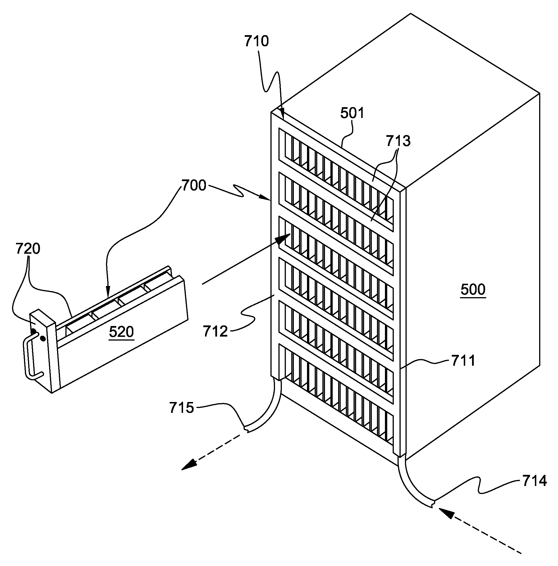
[0023]As used herein, the terms “electronics rack”, “rack-mounted electronic equipment”, and “rack unit” are used interchangeably, and unless otherwise specified include any housing, frame, rack, compartment, blade server system, etc., having one or more heat-generating components of a computer system or electronic system, and may be, for example, a stand alone computer processor having high, mid or low end processing capability. In one embodiment, an electronics rack may comprise multiple electronic subsystems or drawers, each having one or more heat-generating components disposed therein requiring cooling. “Electronic subsystem” refers to any sub-housing, blade, book, drawer, node, compartment, etc., having one or more heat-generating electronic devices disposed therein. Each electronic subsystem of an electronics rack may be movable or fixed relative to the electronics rack, with the rack-mounted electronic drawers and blades of a blade center system being two examples of subsyst...


PUM

PropertyMeasurementUnit
thermally conductiveaaaaaaaaaa
thermal transportaaaaaaaaaa
thermalaaaaaaaaaa

Abstract

Liquid-cooled electronics racks and methods of fabrication are provided wherein a liquid-based cooling apparatus facilitates cooling of electronic subsystems when docked within the electronics rack. The cooling apparatus includes a liquid-cooled cooling structure mounted to a front of the rack, and a plurality of heat transfer elements. The cooling structure is a thermally conductive material which has a coolant-carrying channel for facilitating coolant flow through the structure. Each heat transfer element couples to one or more heat-generating components of a respective electronic subsystem, physically contacts the cooling structure when that electronic subsystem is docked within the rack, and provides a thermal transport path from the heat-generating components of the electronic subsystem to the liquid-cooled cooling structure. Advantageously, electronic subsystems may be docked within or undocked from the electronics rack without affecting flow of coolant through the liquid-cooled cooling structure.

Description

TECHNICAL FIELD[0001]The present invention relates to heat transfer mechanisms, and more particularly, to cooling apparatuses, liquid-cooled electronics racks and methods of fabrication thereof for removing heat generated by one or more electronic subsystems. Still more particularly, the present invention relates to cooling apparatuses and cooled electronics racks comprising a front-mounted, liquid-cooled cooling structure for the electronics rack.BACKGROUND OF THE INVENTION[0002]As is known, operating electronic devices produce heat. This heat should be removed from the devices in order to maintain device junction temperatures within desirable limits, with failure to remove heat effectively resulting in increased device temperatures, potentially leading to thermal runaway conditions. Several trends in the electronics industry have combined to increase the importance of thermal management, including heat removal for electronic devices, including technologies where thermal management...

Claims


Application Information

Patent Timeline
Patent Type & Authority Patents(United States)
IPC IPC(8): H05K7/20F28F7/00H01L23/34
CPCH05K7/20781H05K7/20809Y10T29/49359
Inventor CAMPBELL, LEVI A.CHU, RICHARD C.ELLSWORTH, JR., MICHAEL J.IYENGAR, MADHUSUDAN K.SIMONS, ROBERT E.
Owner LENOVO GLOBAL TECH INT LTD
Why Eureka
Try Eureka