Control method for closed loop operation with adaptive wave form of an engine fuel injector oil or fuel control valve

a technology of engine fuel injector and control valve, which is applied in the direction of valve operating means/release devices, electric control, machines/engines, etc., can solve the problems of inability to efficiently control the supply of fuel to the combustion chamber of the engine, the armature has a tendency to bounce or repeatedly impact against the open coil, and the inability to quickly move the armature away from the open coil. , to achieve the effect of reducing the bounce of the armature at impa

Active Publication Date: 2011-07-26
VITESCO TECH USA LLC
View PDF13 Cites 9 Cited by
  • Summary
  • Abstract
  • Description
  • Claims
  • Application Information

AI Technical Summary

Benefits of technology

An object of an embodiment is to fulfill the need referred to above. In accordance with the principles of the present invention, this objective is achieved by a method of controlling motion of an armature of a fuel injector. The armature is constructed and arranged to move between an open coil and a close coil of the injector. The method applies acceleration current of a certain polarity for a certain amount of time to the open coil with the armature disposed at the close coil. A de-latching current of a polarity opposite of that of the certain polarity is applied for a certain amount of time to the close coil to release magnetic latch on the armature thereby accelerating movement of the armature towards the open coil. A deceleration current is applied for a certain amount of time to the close coil thereby decelerating the armature prior to reaching the open coil. A latching current of the certain polarity is applied for a certain amount of time to the open coil prior to or just after impact of the armature with the open coil to magnetically latch the armature to the open coil thereby reducing bounce of the armature at impact.
In accordance with another aspect of an embodiment, a control system for controlling motion of an armature of a fuel injector includes at least one fuel injector having an armature constructed and arranged to move between an open coil and a close coil, and a controller constructed and arranged to apply 1) acceleration current of a certain polarity for a certain amount of time to the open coil with the armature disposed at the close coil, 2) de-latching current of a polarity opposite of that of the certain polarity for a certain amount of time to the close coil to release magnetic latch on the armature thereby accelerating movement of the armature towards the open coil, 3) deceleration current for a certain amount of time to the close coil thereby decelerating the armature prior to reaching the open coil; and 4) a latching current of the certain polarity for a certain amount of time to the open coil prior to or just after impact of the armature with the open coil to magnetically latch the armature to the open coil thereby reducing bounce of the armature at impact.

Problems solved by technology

However, in such a conventional system, the armature has a tendency to bounce or repeatedly impact against the open coil during the opening stroke.
During this bouncing, it is difficult to control the armature motion and hence results in the inability to efficiently control the supply of fuel to the combustion chamber of the engine.
For example, in conventional systems it is not possible to quickly move the armature away from the open coil in order to minimize the bouncing effect during an injection of a pilot quantity of fuel.
Accordingly, the initial quantity of fuel provided during the pre-stroke event cannot be easily controllable, resulting in a larger injection quantity of fuel than desired.
This may result in a retarded start of injection, as well as the inability to control the armature and hence the injection of a small, pilot quantity of fuel.
That is, during this bouncing or repeated impact, a small quantity of fuel cannot be metered accurately in order to efficiently inject this small quantity of fuel into the combustion chamber of an engine.
Additionally, it is also very difficult, if not impossible, to vary the amount of fuel during this small injection.
Additionally, over time, in the same injector, variations may result from different operating conditions such as temperature and wear on the parts due to aging and other factors.
This also may lead to higher emissions and engine noise.
The shot-to-shot variations mentioned above can cause idle stability issues that are detectable by the vehicle's operator and can cause decreased engine efficiency and increased emissions.

Method used


Image

  • Control method for closed loop operation with adaptive wave form of an engine fuel injector oil or fuel control valve
  • Control method for closed loop operation with adaptive wave form of an engine fuel injector oil or fuel control valve
  • Control method for closed loop operation with adaptive wave form of an engine fuel injector oil or fuel control valve

Examples


Embodiment Construction

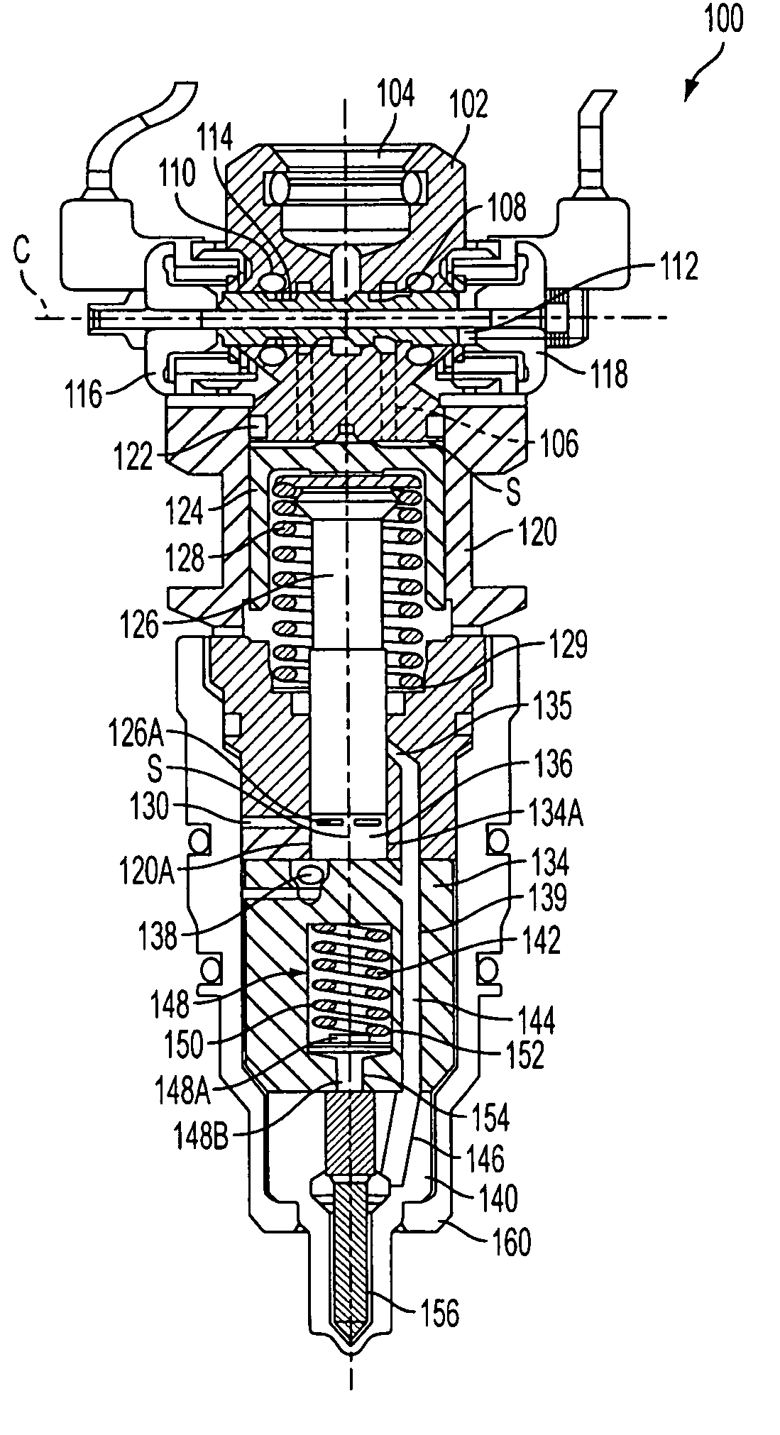
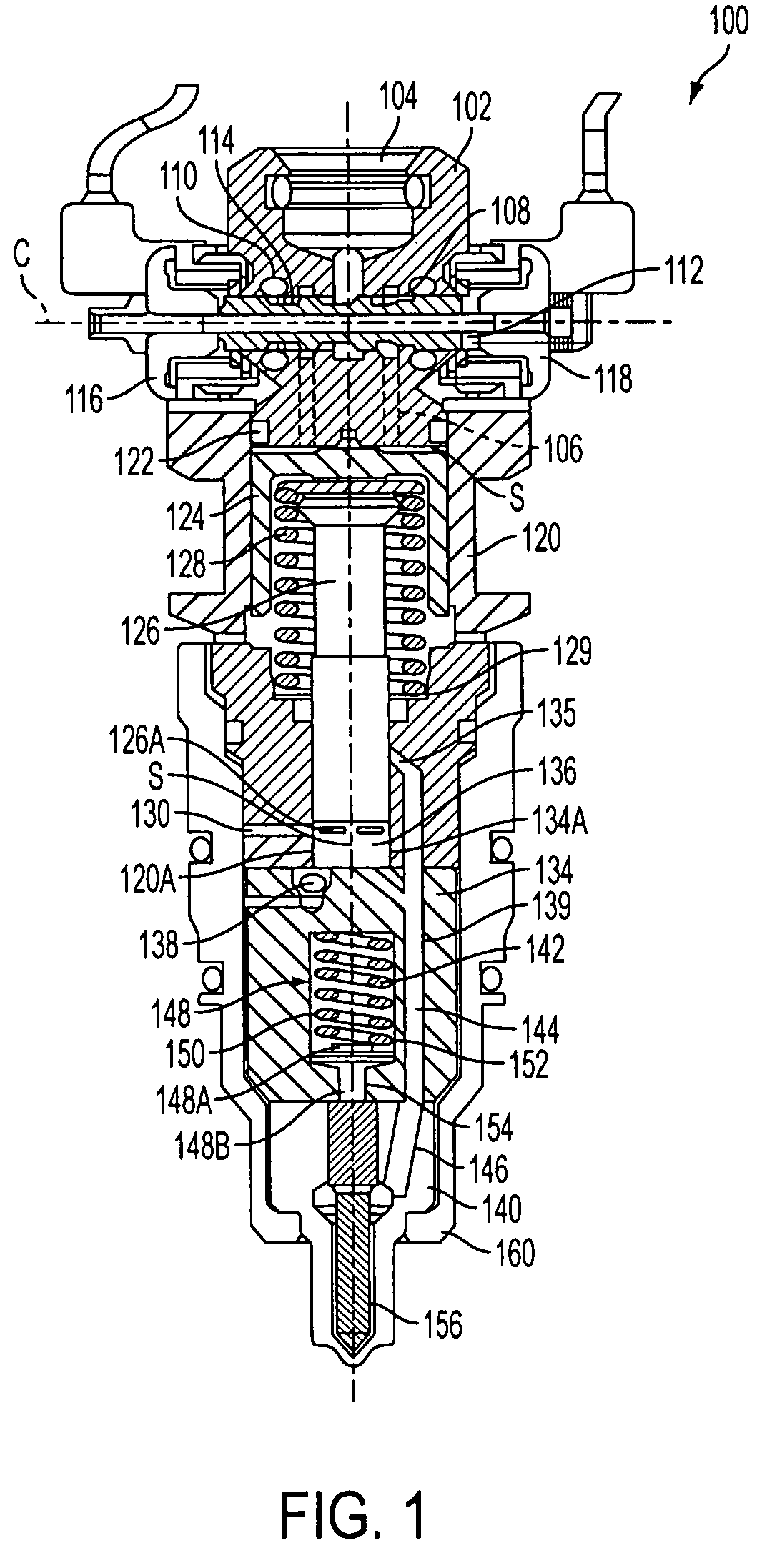
With reference to FIG. 1, an overview of a fuel injector in accordance with the invention is shown. It should be understood, though, that the injector shown in FIG. 1 is provided as one illustrative example, and that other configurations, features and the like may also be equally used with the invention. Accordingly, the fuel injector of FIG. 1 and the features described herein are not to be considered a limiting feature of the embodiment.

The fuel injector, generally indicated at 100, can be of the type disclose din U.S. Pat. No. 7,216,630 B2, the content of which is hereby incorporated by reference into this specification. The fuel injector 100 includes a control valve body 102 as well as an intensifier body 120 and a nozzle 140. The control valve body 102 includes an inlet area 104 which is in fluid communication with working ports 106. At least one groove or orifice (hereinafter referred to as grooves) 108 is positioned between and in fluid communication with the inlet area 104 a...


PUM


Abstract

A method and system controls motion of an armature 112 of a fuel injector 100. The armature moves between an open coil 118 and a close coil 116 of the injector. Acceleration current of a certain polarity is applied to the open coil 118 with the armature disposed at the close coil 116. De-latching current of a polarity opposite of the certain polarity is applied to the close coil 116 to release magnetic latch on the armature thereby accelerating movement of the armature towards the open coil 118. Deceleration current is applied the close coil 116 thereby decelerating the armature prior to reaching the open coil. Latching current of the certain polarity is applied to the open coil 118 prior to or just after impact of the armature 112 with the open coil 118 to magnetically latch the armature to the open coil 118 thereby reducing bounce of the armature at impact.

Description

FIELD OF THE INVENTIONThis invention relates to oil activated fuel injectors and, more particularly, to a system and method to control motion of an armature of the injector using closed loop operation with adaptive current or voltage wave forms.BACKGROUND OF THE INVENTIONIn hydraulically actuated fuel injection systems, a control valve body is provided with a valve system having grooves or orifices which allow fluid communication between working ports, high pressure ports, and venting ports of the control valve body of the fuel injector and the inlet area. The working fluid is typically engine oil or other types of suitable hydraulic fluid which is capable of providing a pressure within the fuel injector in order to begin the process of injecting fuel into the combustion chamber.In current configurations, a driver will deliver a current or voltage to an open side of an open coil solenoid. The magnetic force generated in the open coil solenoid will shift an armature into the open pos...

Claims


Application Information

Patent Timeline
Patent Type & Authority Patents(United States)
IPC IPC(8): F02M37/04H01H9/00
CPCF02D41/20F02M57/025F02D2041/2037F02D2041/2079
Inventor STEWART, JR., ROBERT T.DYNES, RICKY LEEWISDOM, BENJAMIN DANIEL
Owner VITESCO TECH USA LLC
Why Eureka
Try Eureka