
Irradiation device and method for the treatment of acne and acne scars

a technology which is applied in the field of irradiation device and acne scar treatment, can solve the problems of modesty and poor results of sigurdsson, who employed only low-level radiation therapy, and achieve the effect of high treatment efficacy

Inactive Publication Date: 2011-07-26
SPECTROMETRIX OPTOELECTRONICS SYST
View PDF23 Cites 5 Cited by
  • Summary
  • Abstract
  • Description
  • Claims
  • Application Information

AI Technical Summary

Benefits of technology

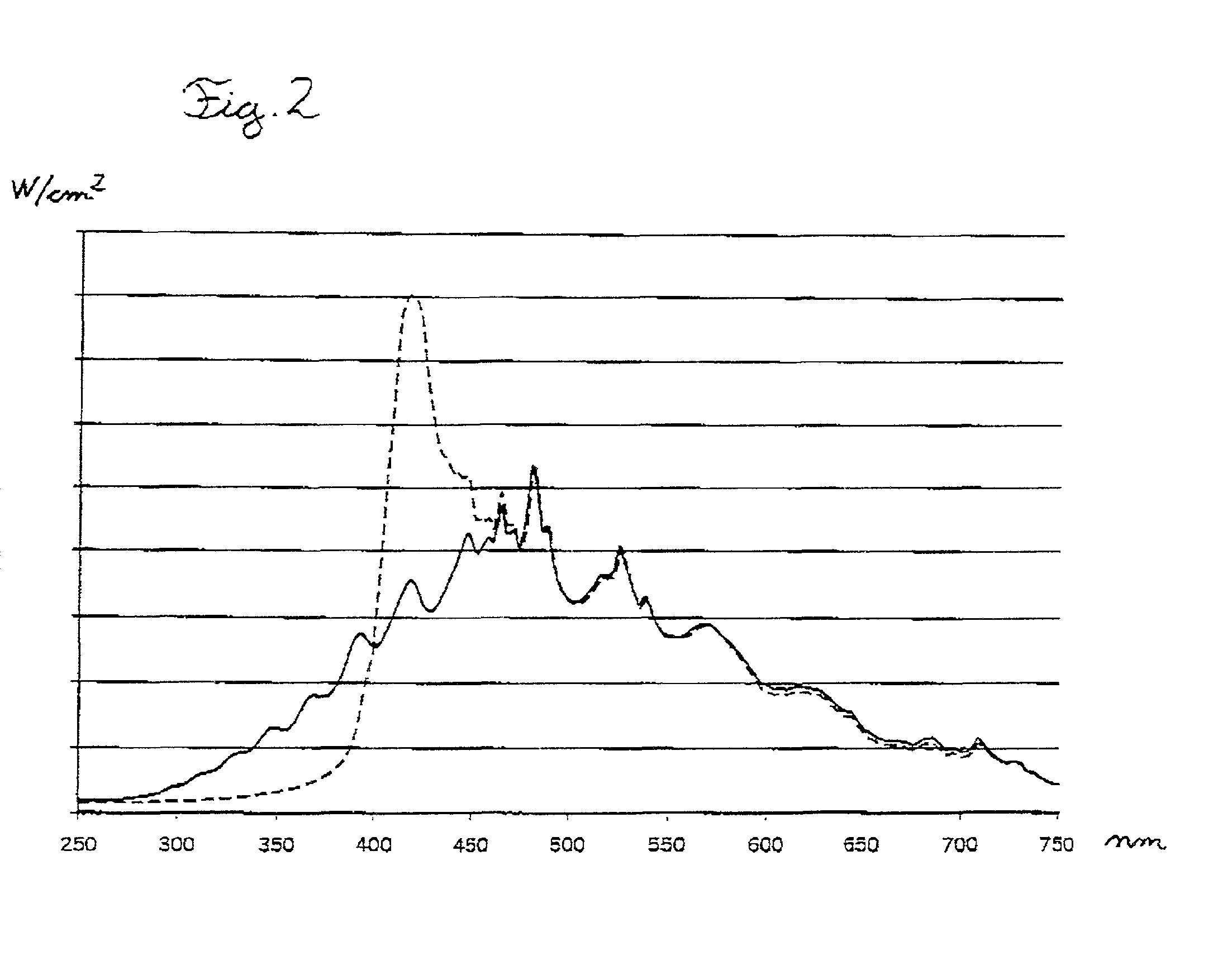
[0018]Unexpectedly, this invention teaches that mean irradiation levels which are one order of magnitude lower than the threshold of 60 mW / cm2 described in WO / 022491 and below the irradiation levels employed by Sigurdsson and Meffert can be very effective if the peak pulse power exceeds the described threshold levels for a short time only. Clinical results show that the efficacy of a pulsed-light acne therapy compared to a cw-treatment with an identical spectrum can be increased by a factor of 10-20. The efficacy of acne therapy described in WO 00 / 02491 possibly relates to the killing of superficial bacteria through the blue part of the spectrum, whereas follicles can only be reached by the aforementioned green and red parts of the spectrum between 520-550 nm resp. 610-670. Pulsed irradiation is much less affected by constant threshold off-set than cw-irradiation, since the fractional contribution of the off-set is much smaller with pulsed irradiation than with cw-radiation. Therefore, the pulsed blue light which reaches the follicle can generate singlet oxygen more efficiently.
[0040]The irradiated area for a mobile system is in the range of 1-200 cm2, since there is an increase in penetration depth if one uses area irradiation in comparison to point irradiation which is advantageous for the reaching of the deeper follicles. A mobile embodiment allows the sequential irradiation of different acne areas, which are normally located in the facial area, the neck area as well as in the area of the upper back and chest.

Problems solved by technology

Therefore, irradiation devices with a pure blue spectral emission have to use high power and even then the results often remain modest.
This possibly explains the poor results of Sigurdsson who employed only low radiation power below or within the range of this threshold.

Method used


Image

  • Irradiation device and method for the treatment of acne and acne scars
  • Irradiation device and method for the treatment of acne and acne scars
  • Irradiation device and method for the treatment of acne and acne scars

Examples


Embodiment Construction

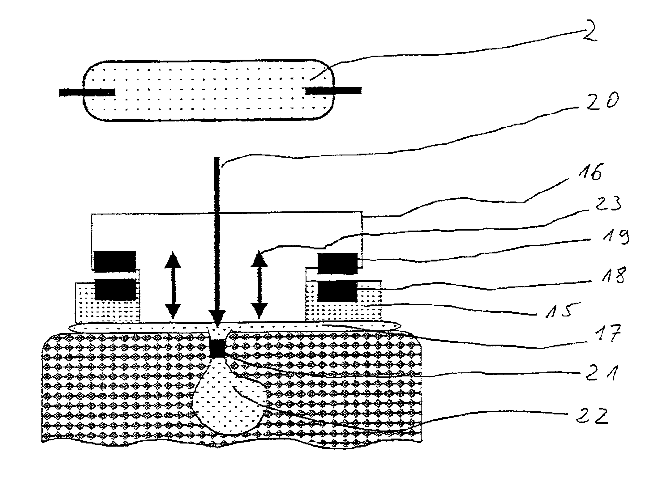
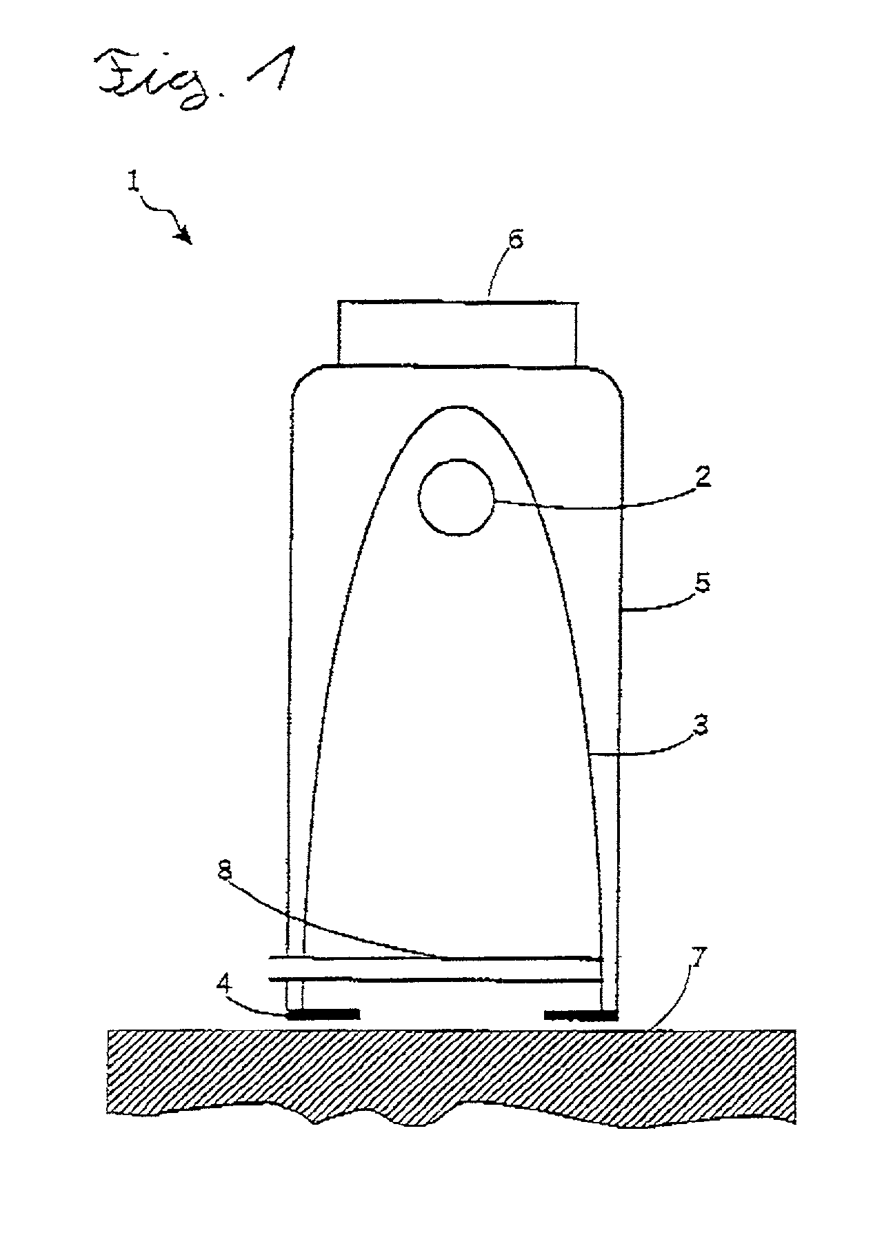
[0055]The irradiation device 1 comprises a broadband irradiation source 2 which is preferably a xenon flashlamp. The irradiation source 2 is mounted in the focus of a parabolic reflector 3 which is open on the side averted from the focus. The exit area at the open end of the parabolic reflector 3 is preferably defined through an adjustable shutter. The adjustable shutter can adjust the area to be irradiated. The irradiation source 2 and the paraboloid reflector 3 are mounted in a housing 5. The housing 5 comprises a handpiece 6 by means of which the irradiation device 1 can be placed on the area to be treated 7. Between the radiation source 2 and the area to be treated 7 there is a luminescent foil 8 arranged which is doped with luminescent particles. The luminescent foil 8 can also be arranged in the proximity of the radiation source 2 or the shutter 4. Preferably, the luminescent foil 8 is arranged in a way that makes it easy to replace. This simplifies the necessary replacement d...


PUM


Abstract

An irradiation device (1) and a method for the treatment of acne and acne scars, comprising at least one source of radiation (2), the source of radiation emitting at least one broadband spectrum in the wavelength range of 320-at least 540 nm and the radiation source (2) being pulseoperable and / or movable relatively to the area to be irradiated, the pulse energy being between 0.05-10 J / cm2 and the peak irradiation intensity being between 0.5 W / cm2 and 100 kW / cm2.

Description

BACKGROUND OF THE INVENTION[0001]1. Field of the Invention[0002]The invention relates to an irradiation device and a method for the treatment of acne.[0003]2. Brief Description of the Related Art[0004]It is known to treat acne, which is a skin disease caused by proliferation of bacteria in blocked follicles of areas of the skin that are rich in sebaceous glands together with keratosis, with blue light in the range of 400-440 nm without significant proportions of UVA, with limited success.[0005]Here we refer to the article of V. Sigurdsson et al., “Phototherapy of Acne Vulgaris with visible Light, Dermatologie 1997, 194; Iss. 3, 256-260” which includes further literature references. This form of therapy started by using red fluorescence of acne follicle as part of the dermatological examination using a woodlamp. The source determined for the fluorescence was the storage of large quantities of porphyrins in the propionbacterium acne. McGinley et al., Facial follicular porphyrin fluore...

Claims


Application Information

Patent Timeline
IPC IPC(8): A61B18/18A61N5/06
CPCA61N5/0616A61N2005/0642A61N2005/0644
Inventor WILKENS, JAN HENNRIKSTIRNER, ROLF
Owner SPECTROMETRIX OPTOELECTRONICS SYST
Learn More