
Wireless network repeater

a repeater and wireless technology, applied in the field of wireless local area networks, can solve the problems of affecting the operational range of the protocol itself, the structure of the protocol itself may be affecting the attenuation problem, and the performance level is rarely realized, if ever, and achieves the effect of facilitating configuration within the network and rapid reconfiguration

Inactive Publication Date: 2011-08-02
QUALCOMM INC
View PDF313 Cites 34 Cited by
  • Summary
  • Abstract
  • Description
  • Claims
  • Application Information

AI Technical Summary

Benefits of technology

[0017]An exemplary frequency translating repeater of the present invention solves the spontaneous transmission problem and the isolation of the transmitter from receiver using a unique frequency detection and translation technique in a WLAN environment. The exemplary repeater allows two or more WLAN units or stations to communicate by translating packets from a first frequency channel, used by one device, to a second frequency channel, used by a second device. The direction of the conversion from channel A to channel B or from channel B to channel A is dynamically configured. The repeater monitors both channels for transmissions and once a transmission on a channel is detected, the repeater is configured to translate the received signal to the other channel, where it is re-transmitted.
[0021]Thus an exemplary repeater in accordance with various embodiments described herein, solve both the isolation issue, allowing a small inexpensive unit, and the spontaneous transmission problem as a repeater it monitors and reacts to channel activity. The exemplary repeater of the present invention further facilitates configuration within a network and rapid reconfiguration if an AP or the network is reconfigured or a new environment is encountered.

Problems solved by technology

While the specifications of products using the above standard wireless protocols commonly indicate data rates on the order of, for example, 11 MBPS and ranges on the order of, for example, 100 meters, these performance levels are rarely, if ever, realized.
Attenuation problems may be exacerbated in the presence of interference in the operating band, such as interference from other 2.4 GHz devices or wideband interference with in-band energy.
Lastly, the structure of the protocols themselves may affect the operational range.
However, problems and complications arise in that for some systems and devices, receivers and transmitters operate at the same frequency as in a WLAN (Wireless Local Area Network) or WMAN (Wireless Metropolitan Area Network) utilizing, for example, 802.11 or 802.16 WLAN wireless protocols.
In such systems, when multiple transmitters operate simultaneously, as would be the preferred case in repeater operation, difficulties arise.
Other problems arise in that, for example, the random packet nature of typical WLAN protocols provides no defined receive and transmit periods.
Because packets from each wireless network node are spontaneously generated and transmitted and are not temporally predictable packet collisions may occur.
An additional complication arising from the use of repeaters in WLAN environments is the random nature of data packet transmissions, which often occur in the various WLAN protocols.
Because transmissions in such an uncoordinated environment are unpredictable in that they may come at any time from any station, the challenge to repeater architectures is significant.
An in addition to challenges associated with collisions, other challenges exist associated with, for example, feedback or the like on channels which are used by more than one repeater.
Although traditional repeaters, such as those used in IS-95 cellular systems, employ directional antennas and physical separation of receive and transmit antennas to achieve the necessary isolation to prevent oscillatory feedback, such a solution is not practical for WLAN repeaters.
The combination of prohibitive costs and the fact that, for indoor environments, isolation is less effective because of reflections caused by objects in close proximity to the antennas, rule out such solutions for indoor WLAN repeaters.
PCT / US03 / 16208 acts in near real time to receive, boost and retransmit packets and while addressing many of the problems in the art, lacks capabilities such as store and forward.
While providing attractive data rate and frequency parameters, the 802.11a repeater is inherently limited in range.
Problems arise due to the range limitations since, while many new applications involving video and audio are only possible using the higher performance available under 802.11a making the use of 802.11a compliant repeaters highly desirable, the range limitations hinder usefulness and limit widespread acceptance.
Such limitations are disappointing since the 802.11a frequency bands are well suited for frequency translation for the above mentioned reasons, and due to the significant amount of allocated spectrum available for use within the band.
It should be noted however, if a repeater is not pre-assigned to operate or “slaved” with a particular AP, difficulties arise since the repeater cannot know which AP to service resulting in feedback problems, erroneous transmissions or significant interference between the repeater or repeaters and various APs in the network.
Pre-programming is limited however, in that dynamic approaches associated with, for example, limiting local interference through power adjustment, as described above, can not be as easily achieved with simple pre-programming.
Moreover, during operation, an AP may be switched to a different channel after repeater configuration due to interference from a new source or from other unforeseeable problems.
Undesirable consequences arise however in that repeaters originally configured at the physical layer for particular frequency channels and the like, as described above would have to be reconfigured, reconnected, or the like to the AP software.
Further problems and issues with repeater configuration arise in connection with regulations promulgated by the European Union (EU) in the form of 802.11h certification requirements.
Thus a conventional repeater would fail to comply with the proposed standards of detecting the presence of RADAR energy when selecting possible repeating channels.
A conventional repeater will experience difficulty knowing which channel the AP is on.
Problems arise however, in that such systems are difficult to implement for the consumer as they require some basic knowledge, or at least data interpretation, of the WLAN parameters.

Method used


Image

  • Wireless network repeater
  • Wireless network repeater
  • Wireless network repeater

Examples


Embodiment Construction

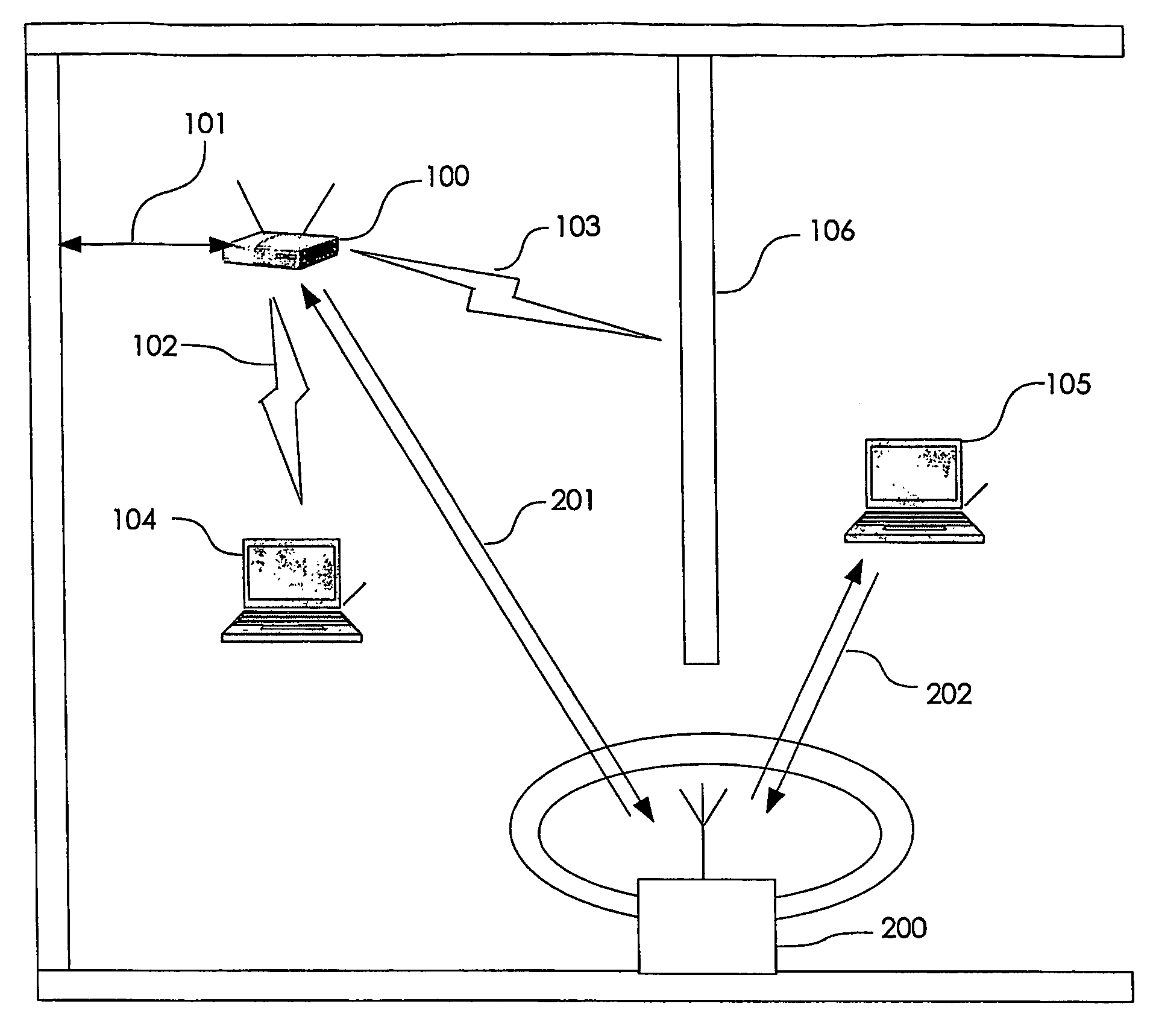
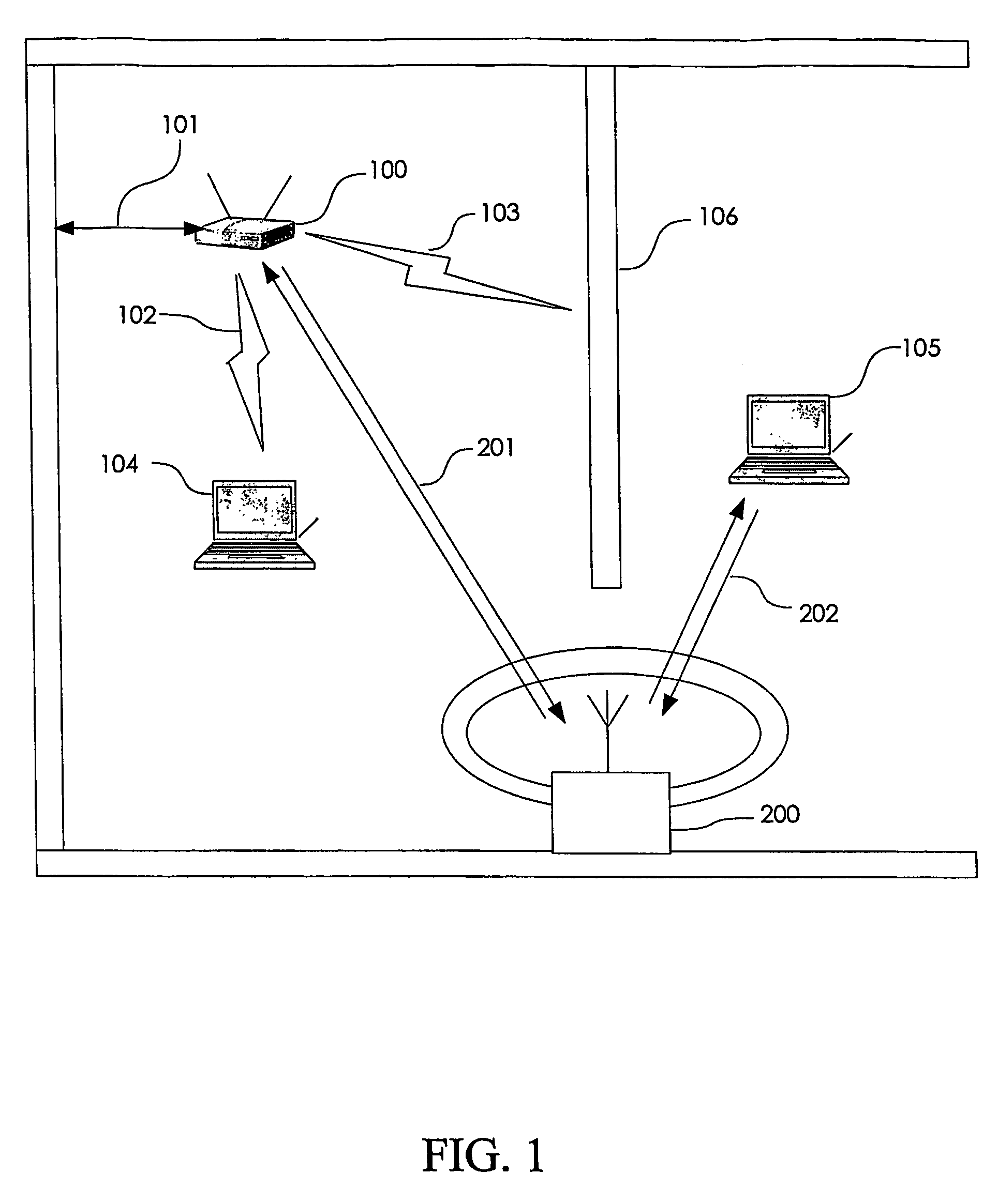
[0029]Referring now to FIG. 1, a wide area connection 101, which could be, for example, an Ethernet connection, a T1 line, a wideband wireless connection or any other electrical connection providing a data communications path, may be connected to a wireless gateway, or access point (AP) 100. The wireless gateway 100 sends RF signals, such as IEEE 802.11 packets or signals based upon Bluetooth, Hyperlan, or other wireless communication protocols, to client units 104, 105, which may be personal computers, personal digital assistants, or any other devices capable of communicating with other like devices through one of the above mentioned wireless protocols. Respective propagation, or RF, paths to each of the client units 104, 105 are shown as 102, 103.

[0030]While the signal carried over RF path 102 is of sufficient strength to maintain high-speed data packet communications between the client unit 104 and the wireless gateway 100, the signals carried over the RF path 103 and intended fo...


PUM


Abstract

A frequency translating repeater (250) for use in a time division duplex radio protocol communications system includes a processor (260), a bus (261), a memory (262), an RF section (264), and an integrated station device (264). An access point (210) is detected based on information transmitted frequency channels using a protocol. Detection is initiated automatically during a power-on sequence or by activating an input device such as a button. Frequency channels are scanned for a beacon signal and an access point chosen as a preferred access point based on a metric such as power level.

Description

CROSS REFERENCE TO RELATED APPLICATIONS[0001]This application is related to and claims priority from pending U.S. Provisional Application No. 60 / 433,171 filed Dec. 16, 2002, and is further related to PCT Application PCT / US03 / 16208 entitled WIRELESS LOCAL AREA NETWORK REPEATER, the contents of which are incorporated herein by reference.FIELD OF THE INVENTION[0002]The present invention relates generally to wireless local area networks (WLANs) and, particularly, the present invention relates to channel selection for a frequency translating repeater connecting to an Access Point (AP).BACKGROUND OF THE INVENTION[0003]Because of increasing popularity, there is an ongoing need to extend the range of wireless local area networks (WLAN), including but not limited to WLANs described and specified in the 802.11, 802.16 and 802.20 standards. While the specifications of products using the above standard wireless protocols commonly indicate data rates on the order of, for example, 11 MBPS and ran...

Claims


Application Information

Patent Timeline
Patent Type & Authority Patents(United States)
IPC IPC(8): H04J3/08H04L12/28H04W16/26H04W48/20
CPCH04B7/026H04B7/15542H04W16/26H04W84/047H04L41/0213H04W48/20
Inventor PROCTOR, JR., JAMES A.GAINEY, KENNETH M.
Owner QUALCOMM INC
Learn More