Multi-axis magnetic lens

a magnetic lens and charged particle technology, applied in the direction of beam deviation/focusing, magnetic discharge control, instruments, etc., can solve the problems of reducing the high order harmonics of magnetic fields, weakening non-axis, etc., and achieve the effect of a wider range of applicability

Active Publication Date: 2011-08-23
ASML NETHERLANDS BV
View PDF3 Cites 24 Cited by
  • Summary
  • Abstract
  • Description
  • Claims
  • Application Information

AI Technical Summary

Benefits of technology

The present invention relates to a multi-axis magnetic lens for a charged particle beam system. The apparatus eliminates the undesired non-axisymmetric transverse magnetic field components called as high order harmonics from the magnetic field generated by a common excitation coil and leaves the desired axisymmetric field called as round lens field for focusing each particle beam employed within the system. However, it would be recognized that the invention has a much broader range of applicability.
The seventh embodiment replaces the magnetic shielding tubes or the magnetic shielding house that locates below the lower magnetic conductor plate to a magnetic shielding plate to gain a small working distance between the apparatus and the specimen.

Problems solved by technology

This design weakens the non-axisymmetric distribution of magnetic scalar potential inside each magnetic ring and as a result reduces the high order harmonics of the magnetic fields.

Method used


Image

  • Multi-axis magnetic lens
  • Multi-axis magnetic lens
  • Multi-axis magnetic lens

Examples


first embodiment

the present invention inserts a much higher permeability magnetic insert ring into each hole of each sub-lenses to weaken the non-axisymmetric distribution of magnetic scalar potential in the sub-lens, and as a result reduces high order harmonics of the transverse magnetic field. The structure of this embodiment is illustrated in FIG. 3A and called as Model 2. A magnetic conductor ring 310 is inserted in hole 8, in the upper plate 40 and its permeability is much higher than that of the magnetic conductor plates 40. For example the permeability of the magnetic insert ring is 100,000 versus the permeability of the magnetic conductor plate of 5,000. In this embodiment, the magnetic insert rings 310 inserted in the upper and lower magnetic conductor plates function as a pair of pole pieces of the sub-lens. A simulation result of the dipole field distribution on the optical axis 35 of the sub-lens 30 is illustrated in FIG. 3B, wherein permeability of plates 40, 41 is 5000, coil york 230 ...

second embodiment

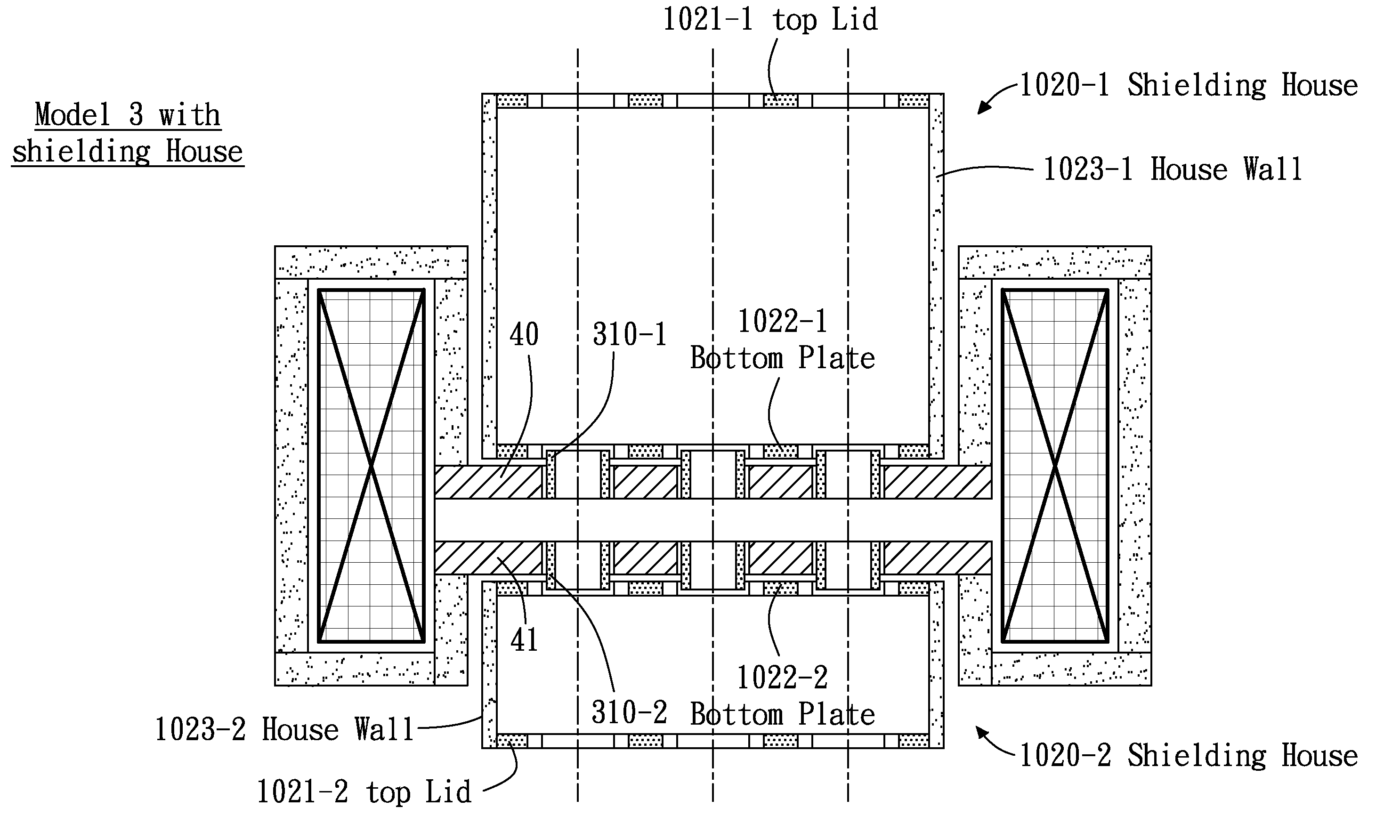
the present invention inserts a much higher permeability magnetic insert ring and a non-magnetic material gap into each hole of each sub-lens. The magnetic insert ring is aligned with the hole. The structure of this embodiment is illustrated in FIG. 4A and called as Model 3. A non-magnetic material gap 420 is introduced between the inner sidewall of hole 8 and the outer sidewall of the magnetic insert ring 310. For example, the non-magnetic gap 420 is a gap of vacuum, or filled with a ring of non-magnetic material such as aluminum, copper, and ceramics. A simulation result of the dipole field distribution on the optical axis 35 of the sub-lens 30 is illustrated in FIG. 4B, wherein permeability of plates 40, 41 is 5000, coil york 230 is 1000, and magnetic insert ring 310 is lowered to 5000. Introducing a non-magnetic material gap 420 effectively reduces the dipole field between R1 and R4. The permeability of the magnetic insert ring 310 needs not be very high, for example 5000 instea...

third embodiment

the present invention is illustrated in FIG. 5A. Two stack magnetic shielding tubes 530, respectively called as 530-1 and 530-2, are introduced to the system. This design is for removing the magnetic field in the area above the upper magnetic conductor plate 40 and below the lower magnetic conductor plate 41. Each magnetic shielding tube 530 with an inner diameter equal or larger than the non-magnetic material gap 420 is separated from the magnetic conductor plate 40, 41 by a non-magnetic lining 520 and aligned with the corresponding magnetic insert ring 310. Four more markers are added to the drawing. T1 and T2 respectively correspond to the position inside and at the bottom end of the magnetic shielding tube 530-1 located above the upper magnetic conductor plates 40. T3 and T4 respectively correspond to the positions at the top end of and inside the magnetic shielding tube 530-2 located below the lower magnetic conductor plate 41. A simulation result of the dipole field distributi...


PUM


Abstract

The present invention relates to a multi-axis magnetic lens for a charged particle beam system. The apparatus eliminates the undesired non-axisymmetric transverse magnetic field components from the magnetic field generated by a common excitation coil and leaves the desired axisymmetric field for focusing each particle beam employed within the system.

Description

CROSS-REFERENCE TO RELATED APPLICATIONSNOT APPLICABLESTATEMENT AS TO RIGHTS TO INVENTIONS MADE UNDER FEDERALLY SPONSORED RESEARCH AND DEVELOPMENTNOT APPLICABLEREFERENCE TO A “SEQUENCE LISTING,” A TABLE, OR A COMPUTER PROGRAM LISTING APPENDIX SUBMITTED ON A COMPACT DISKNOT APPLICABLEFIELD OF THE INVENTIONThe present invention relates to a multi-axis magnetic lens for a charged particle beam system. More specifically, it relates to a charged particle optics apparatus with a non-magnetic material gap between a magnetic insert ring and a magnetic conductor plate for eliminating non-axisymmetric transverse magnetic field due to asymmetric structure of a plurality of charged particle beams.BACKGROUND OF THE INVENTIONDefect inspection of semiconductor wafers and masks for IC manufacturing is an accepted production process for yield enhancement. The information obtained from a wafer defect inspection tool can be used to flag defective dies for repair, or improve wafer processing parameters....

Claims


Application Information

Patent Timeline
Patent Type & Authority Patents(United States)
IPC IPC(8): H01J1/50
CPCH01J37/141H01J2237/1405G21K1/08
Inventor CHEN, ZHONGWEIREN, WEIMINGKANAI, KENICHILIU, XUEDONG
Owner ASML NETHERLANDS BV
Why Eureka
Try Eureka