Closed loop scroll expander engine

a scroll expander and expander technology, applied in combination engines, machines/engines, mechanical equipment, etc., can solve the problems of significant green house and carbon fuel emission, limited power density, and serious vibration and noise, and achieves a wide range of energy outputs, easy maintenance, and low weight

Active Publication Date: 2011-08-30
SECCO2 ENGINES
View PDF38 Cites 24 Cited by
  • Summary
  • Abstract
  • Description
  • Claims
  • Application Information

AI Technical Summary

Benefits of technology

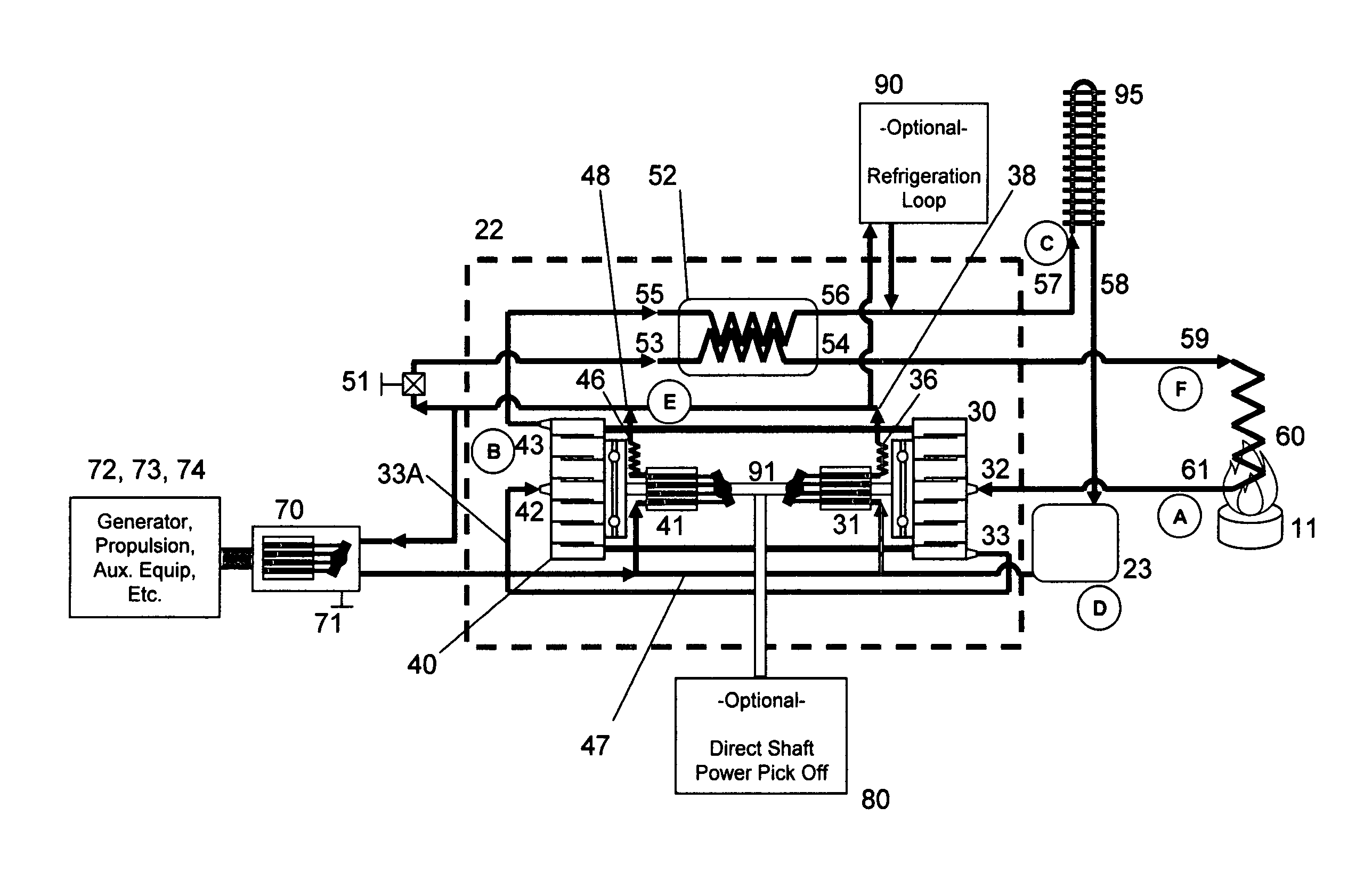
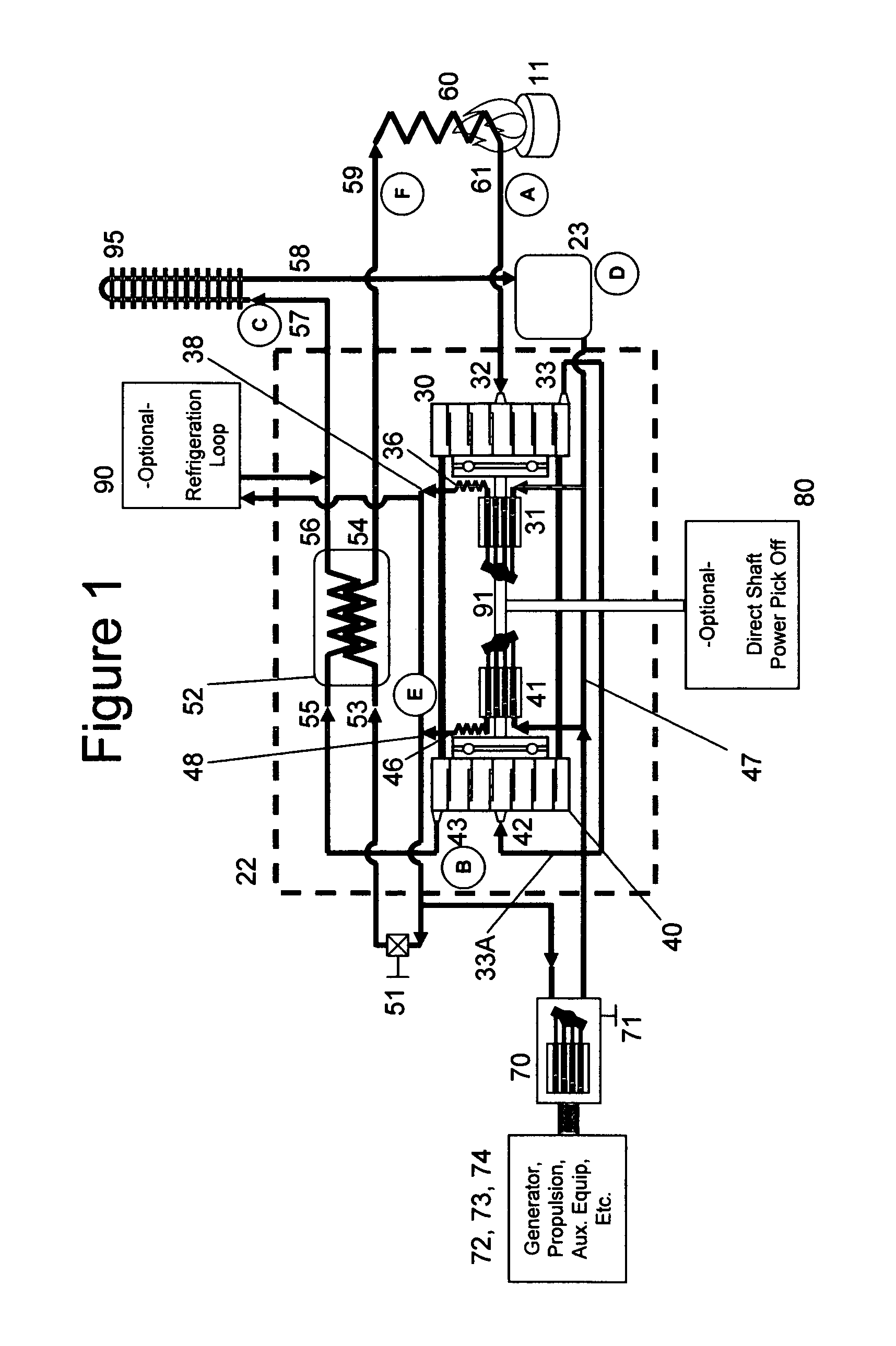
[0031]In the preferred embodiment, a pair of scroll expanders connected by a common shaft is used for a low weight, small package device that is able to produce a variety of power conversion means. In the preferred embodiment, the orbital shaft's rotations provide the power to operate at least one variable displacement pump. By using a variable displacement pump as a means for converting mechanical energy to hydraulic or fluid energy, the working fluid operating pressure is easier to maintain and a wider variety of energy outputs can be realized.

Problems solved by technology

There are significant limitations associated with using these types of internal combustion engines, including: a efficiencies of approximately 20% to 30%; a limited type of fuel associated with each type of engine; serious vibration and noise associated with cams, camshafts and piston rods; power density limitations; significant green house and carbon fuel emission associated with internal combustion engines; and limitations associated with operations of an internal combustion engine at limited air density environments (Brayton cycle turbines have this limitation as well).
While these engines are well understood and well developed, it is also known that these engines produce much less power than their theoretical limits due to the limitations association with the friction, heat loss and the timing associated with the combustion of the fuel and air mixture within the cylinder of an engine block.
These limitations can also limit the ability to control the quality of combustion and the range of air to fuel mixtures that can be ignited.
It is well known that these engines decrease delivered power as the atmospheric density of air decreases with altitude and the air temperature increases because the net mass flow of air available to the engine decreases.
From a theoretical stand point both the Stirling and Ericsson cycles potentially achieve efficiency near the absolute limit, defined by the efficiency of a Carnot cycle; however, in actual practice these cycles require isothermal compression and expansion of the working fluid.
The physical means for achieving an isothermal process in compression and expansion is bulky, involves friction losses, and is limited by the power rate that can be achieved with heat exchangers.
This has proven to make these types of heat engines heavy for the power they produce and do not achieve their desired theoretical efficiency.
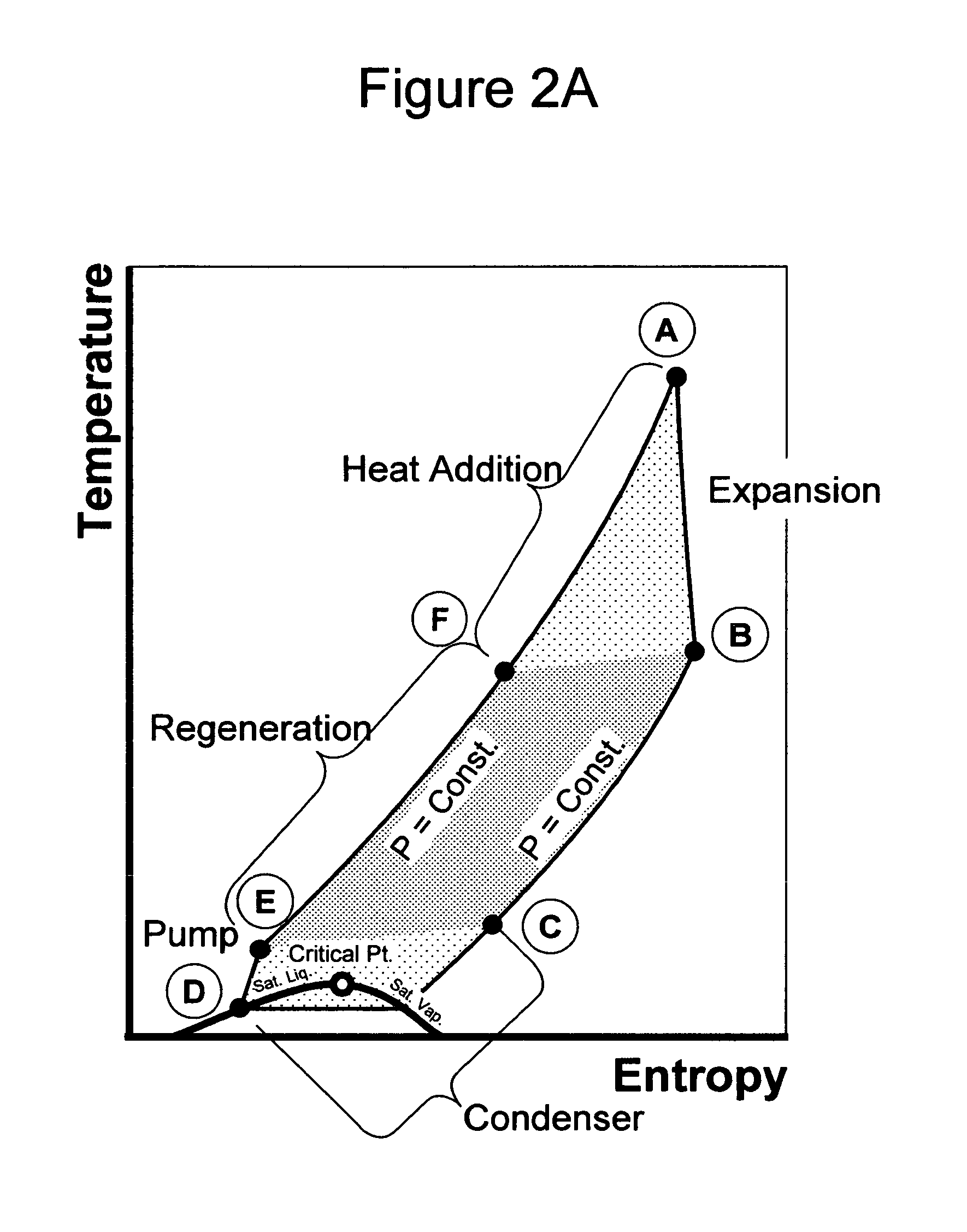
The patent, while describing the benefits of using a supercritical working fluid at a low cycle pressure substantially above critical pressure and a temperature below critical temperature, still lacks detail on how to effectively accomplish this process for a high pressure high temperature working fluid in a relatively small, lightweight package.
For working fluids like air, Helium, or Nitrogen this lack of phase change is appropriate since the pressures and temperatures required to enable a phase change are impractical.
There are practical challenges to using CO2 as a working fluid because of its high critical pressure, yet relatively low critical temperature.
For extracting heat from combustion, the pressure of the fuel and air mixture is not as critical and often not desired to be too high.

Method used


Image

  • Closed loop scroll expander engine
  • Closed loop scroll expander engine
  • Closed loop scroll expander engine

Examples


Embodiment Construction

[0040]Various embodiments of the invention will now be described. The following descriptions provide specific details for a thorough understanding and enabling description of these embodiments. It should be noted, however, that the above “Background” describes technologies that may enable aspects and embodiments of the invention. One skilled in the relevant arts will understand, however, that the invention may be practiced without many of these details. Additionally, some well-known structures or functions may not be shown or described in detail, so as to avoid unnecessarily obscuring the relevant description of the various aspects and embodiments of the invention.

[0041]The terminology used in the description presented below is intended to be interpreted in its broadest reasonable manner, even though it is being used in conjunction with a detailed description of certain specific embodiments of the invention. Certain terms may even be emphasized herein; however, any terminology inten...


PUM


Abstract

Apparatuses and methods related to an engine for converting heat into mechanical output using a working fluid in a closed circulating system are disclosed. In some embodiments, the engine includes a pump to pressurize the working fluid, a regenerative heat exchanger to transfer heat from a first portion of the working fluid to a second portion, a heating device to heat the working fluid, and first and second scroll expanders to expand the working fluid and generate the mechanical output. Other embodiments may be described and claimed.

Description

STATEMENT OF GOVERNMENT INTERESTS[0001]This invention was made with Government support under contract W31P4Q-09-C-0112 awarded by the U.S. Army. The Government has certain rights in the invention.CROSS REFERENCE TO RELATED APPLICATION[0002]None.BACKGROUND OF THE INVENTION[0003]The present invention generally relates to the methods and devices for high efficient power conversion by means of an externally heated closed loop regenerative heat engine which utilizes high pressure fluid, preferably carbon dioxide, through at least one scroll expander for the co-generation of shaft power, fluid power or refrigeration.[0004]Currently the state of the art for engines are dominated by internal combustion engines based upon open-loop Otto cycle, Diesel cycle, or Brayton thermodynamic power cycles. Engines based upon these cycles have proven to be sufficiently efficient for many applications and the current state of the art including the benefits and detriments of the various types of engines i...

Claims


Application Information

Patent Timeline
Patent Type & Authority Patents(United States)
IPC IPC(8): F01K7/34
CPCF01C1/0215F01C11/004F04C2210/1027F04C2210/1072
Inventor CARTER, PRESTON HENRY
Owner SECCO2 ENGINES
Why Eureka
Try Eureka