
Light-filtering module and projecting system applied therewith

a technology of projector and light filtering module, applied in the field of light filtering module, can solve the problems of inability to provide precise color performance and high brightness output of projector, and the color performance of brief-report projector may be hindered, and achieve the effect of high brightness output and precise color performan

Inactive Publication Date: 2011-09-06
ASIA OPTICAL INT LTD
View PDF3 Cites 5 Cited by
  • Summary
  • Abstract
  • Description
  • Claims
  • Application Information

AI Technical Summary

Benefits of technology

"The invention provides a light-filtering module that can switch between a high-brightness output mode and a precise-color output mode in a projector system. This module includes a dichroic mirror and a first image unit that produces the first colored light. A light-filtering unit is located between the dichroic mirror and the first image unit and can switch between a wide-wavelength spectrum and a narrow-wavelength spectrum. This allows for the high brightness output when the light-filtering unit is in the first status and the precise-color output when the light-filtering unit is in the second status. The technical effect of this invention is to provide both high brightness and precise color performance in a projector system."

Problems solved by technology

However, due to 550 nm wavelength of green light contained with the yellow light, color performance of brief-report projectors may be hindered, as the green light contained with the yellow light is incorporated with lights containing real colors.
Based on the described features of the home-theatre and brief-report projectors, there is no projector capable of providing precise color performance and high brightness output.

Method used


Image

  • Light-filtering module and projecting system applied therewith
  • Light-filtering module and projecting system applied therewith
  • Light-filtering module and projecting system applied therewith

Examples


first embodiment

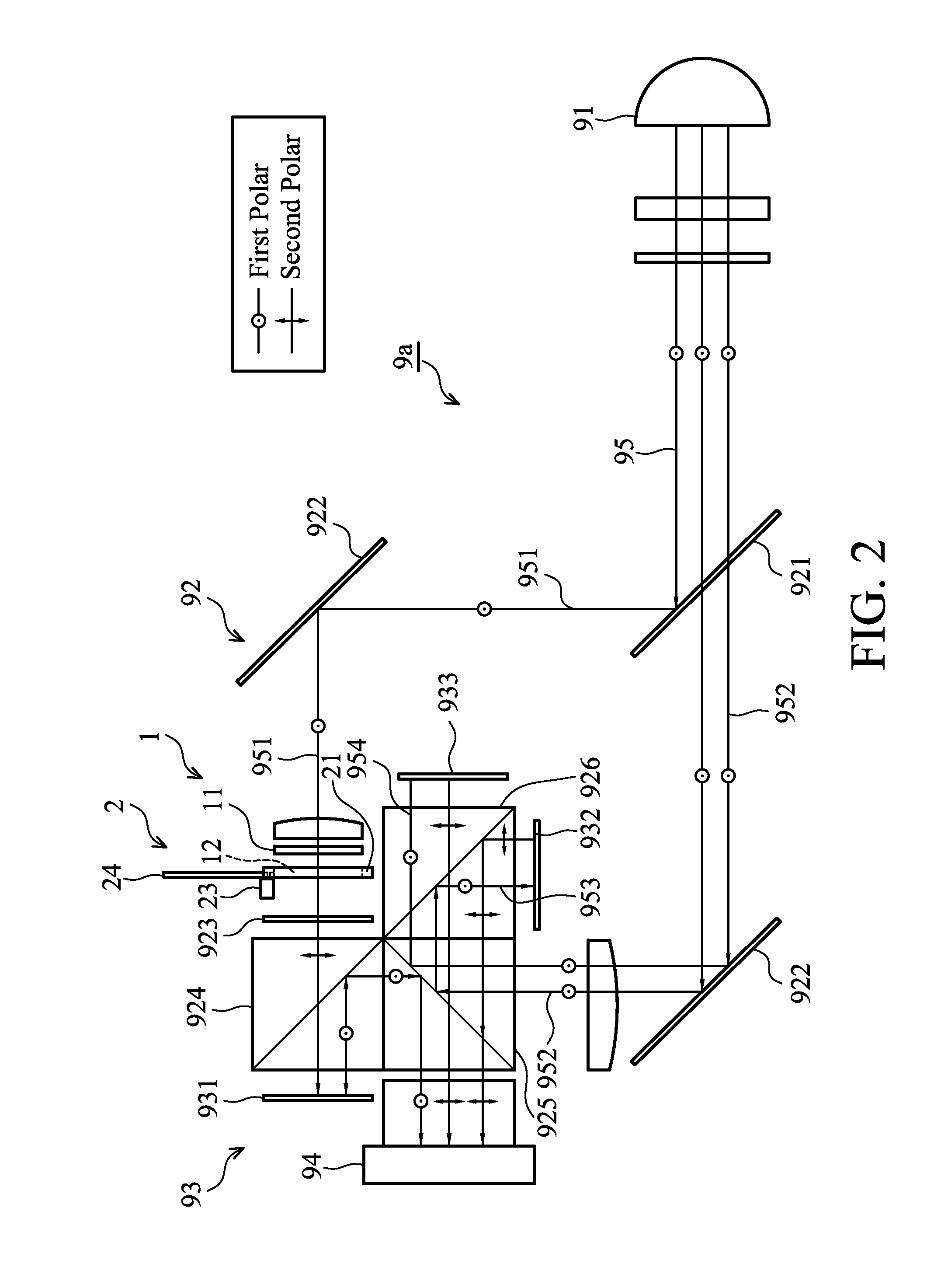
[0021]In FIGS. 2 and 3, a light-filtering module of a first embodiment is applied in a projecting system 9a. The projecting system 9a comprises a light-source module 91, a light-management module 92, a signal module 93 and a projecting lens 94.

[0022]The light-source module 91 outputs a white light beam 95 characterized with a first polar. The light-management module 92 comprises a dichroic mirror 921, a plurality of reflecting parts 922, a phase plate 923, a first polar beam-splitter 924, a second polar beam-splitter 925 and a dichroic prism 926. The dichroic mirror 921 is utilized to divide the white light beam 95 into a first colored light 951 and a dual colored light 952. The reflecting parts 922 are utilized to reflect the first colored light 951 and the dual colored light 952, respectively. The first colored light 951 characterized with the first polar is converted into the first colored light 951 characterized with the second polar by the phase plate 923, and the first colored...

second embodiment

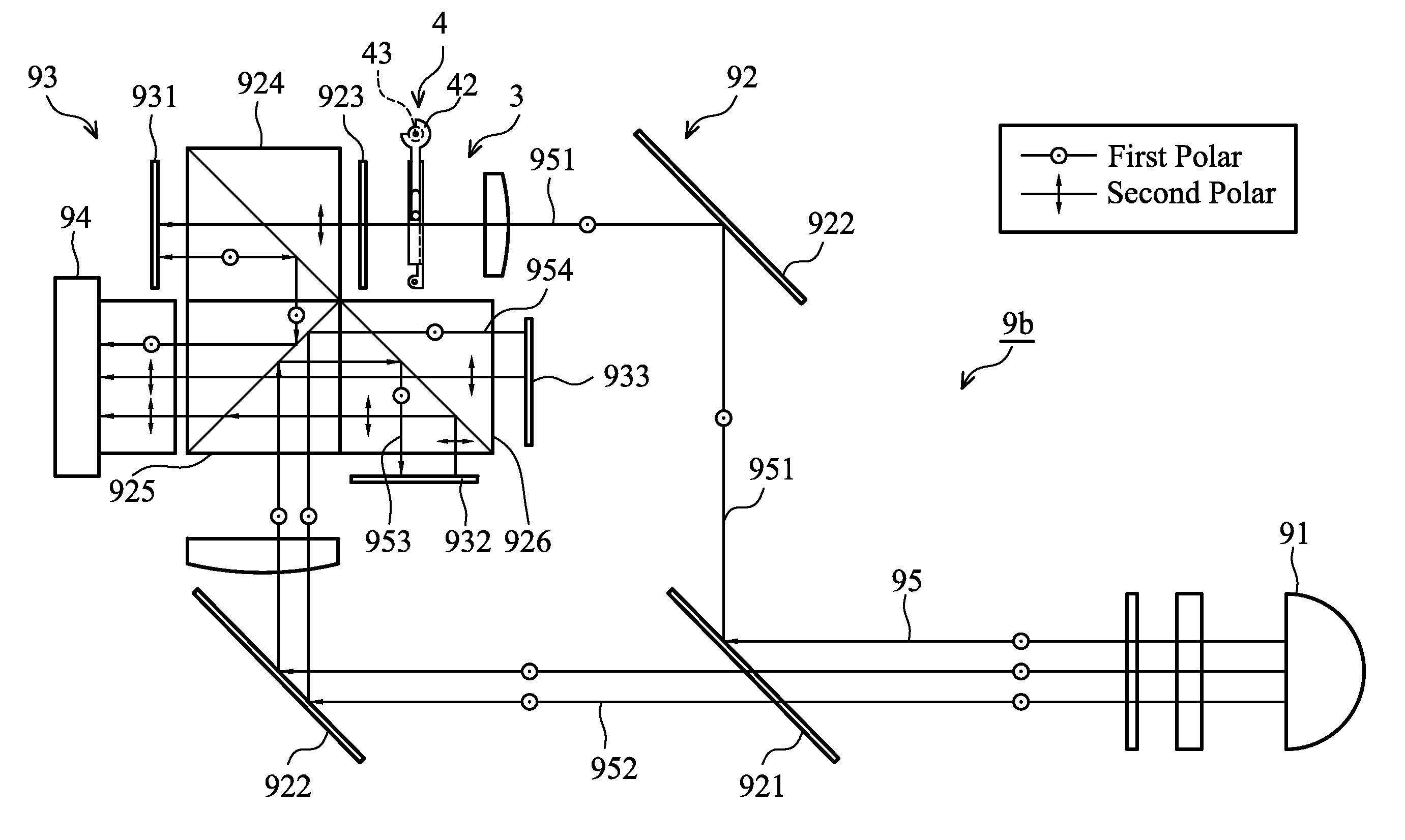
[0034]The following description is directed to the conversion of the high-brightness output mode and precise-color output mode provided by the projecting system 9b of the

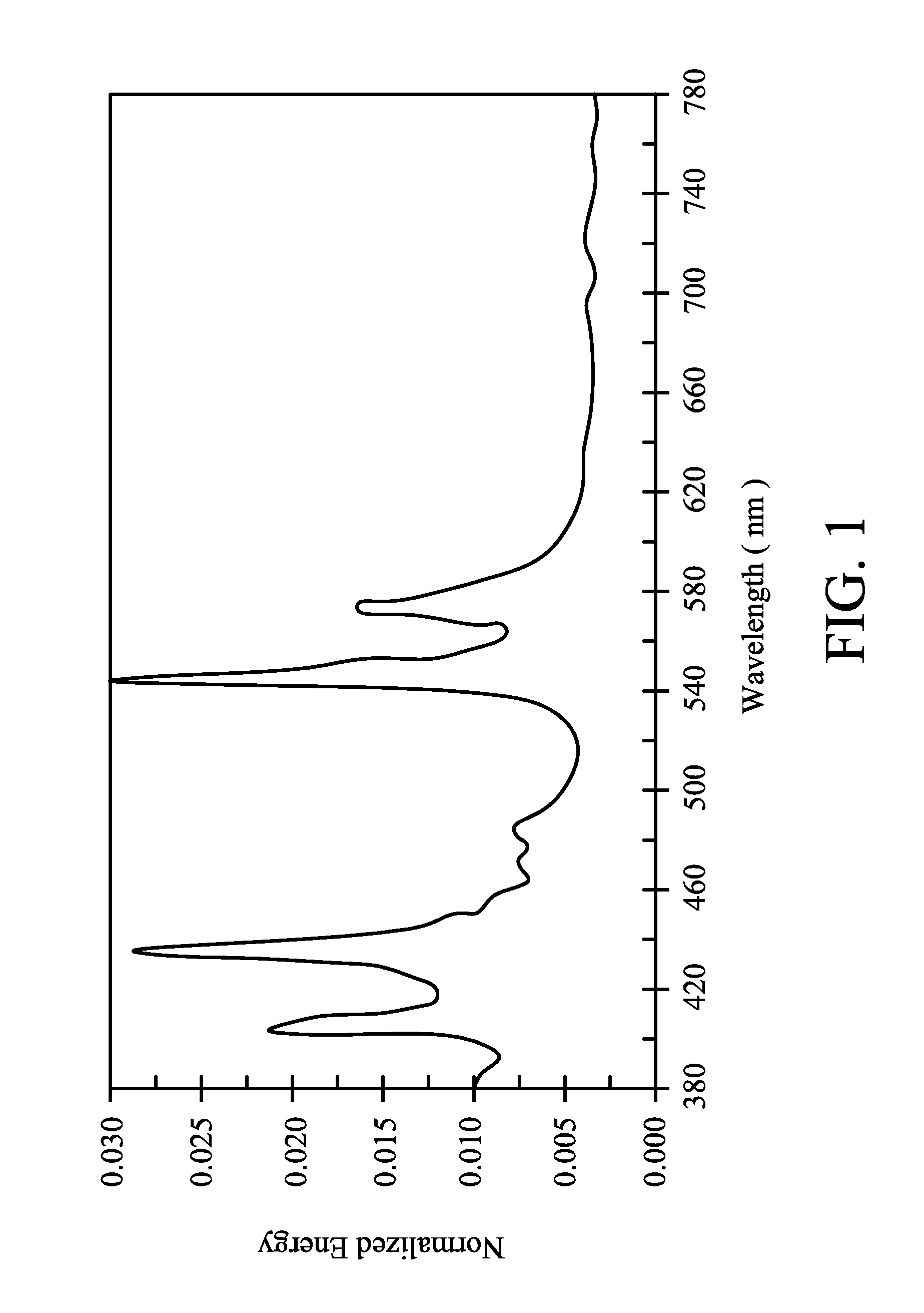
[0035]In FIG. 5, when the output mode of the projecting system 9b determined by the user is the high-brightness output mode, the coupling element 42 driven by the driving element 43 is rotated, moving the end 421 thereof along the slot 412 of the frame 41 to approach the supporting portion 411 of the frame 41, to cause the band-pass filter 31 to be disposed on the frame 41 perpendicular to the light path of the first colored light 951. With respect to the wide-wavelength spectrum of the band-pass filter 31, the high energy peaks of 550 nm wavelength of green light and 570 nm wavelength of yellow light shown in FIG. 1 are allowed to penetrate the band-pass filter 31 and are directly output to the following phase plate 923. Based on the description above, it is understood that the light-filtering unit 3 presently is d...


PUM


Abstract

A light-filtering module includes a light-source module, a dichroic mirror and a first image unit. The light-source module outputs a light beam. The dichroic mirror divides the light beam into a first colored light and a dual colored light. The first image unit provides the first colored light with image information. The light-filtering module includes a light-filtering unit and a driving unit. The light-filtering unit is located between the dichroic mirror and the first image unit is located at a light path of the first colored light. The driving unit includes a coupling element coupled to the light-filtering unit and a driving element utilized to drive the coupling element. The driving element drives the light-filtering unit, switching between a first status and a second status by the coupling element. A wide-wavelength spectrum and a narrow-wavelength spectrum are provided when the light-filtering unit is in the first and second statuses, respectively.

Description

CROSS REFERENCE TO RELATED APPLICATIONS[0001]This Application claims priority of Taiwan Patent Application No. 096139869, filed on Oct. 24, 2007, the entirety of which is incorporated by reference herein.BACKGROUND OF THE INVENTION[0002]1. Field of the Invention[0003]The invention relates to a light-filtering module, and more particularly to a light-filtering module applied in a projecting system.[0004]2. Description of the Related Art[0005]When projectors are in use, output effects are required for particular situations, such as home theatre projectors with real color and brief report projectors with high brightness.[0006]FIG. 1 is a spectrum energy distribution diagram of a UHP light source. For visible light within the range between 380-780 nm wavelength, two high energy peaks of 550 nm wavelength of green light and 570 nm wavelength of yellow light, are characterized with the following features when used in projectors for different applications.[0007]For home-theatre projectors ...

Claims


Application Information

Patent Timeline
Patent Type & Authority Patents(United States)
IPC IPC(8): G03B21/14G02B27/14G02B5/22G03B21/32
CPCG03B21/14G03B21/2053G03B33/12
Inventor HSIUNG, CHIEN-CHIHWU, TZU-LUNGLIN, KENG-HUIHUNG, WEN-LANGPENG, WEI-HSIANGKE, CHAO-YANGHUNG, YI-CHUNG
Owner ASIA OPTICAL INT LTD
Learn More