Optimized nutrient removal from wastewater

a technology for removing nutrient and wastewater, applied in the direction of biological water/sewage treatment, sustainable biological treatment, membrane technology, etc., can solve the problems of increasing the cost of energy consumption contributing substantially to the cost of energy usage of wastewater treatment plants, and requiring high concentrations of dissolved oxygen, so as to promote the development of bacterial populations, and reduce ammonia in streams

Active Publication Date: 2011-09-06
AMERICAN WATER WORKS
View PDF22 Cites 35 Cited by
  • Summary
  • Abstract
  • Description
  • Claims
  • Application Information

AI Technical Summary

Benefits of technology

Embodiments of the invention are defined by the claims below, not this summary. A high-level overview of various aspects of the invention are provided here for that reason, to provide an overview of the disclosure, and to introduce a selection of concepts that are further described in the detailed-description section below. This summary is not intended to identify key features or essential features of the claimed subject matter, nor is it intended to be used as an aid in isolation to determine the scope of the claimed subject matter.
In a first aspect, a method is provided for reducing ammonia in a stream. The method includes providing a stream containing ammonia and contacting the ammonia-containing stream with an oxygen-containing stream under effective treatment conditions to form a first product stream. The ratio of ammonia in the ammonia-containing stream to oxygen in the oxygen-containing stream being about 2.28 g O2/g N—NH3 (2.28 grams of oxygen per gram of nitrogen in ammonia) or less. Further, the method includes exposing the first product stream to organic matter under effective treatment conditions in a ratio of about 0.57 g COD/g N—NH3 (0.57 grams of chemical oxygen demand (COD) per gram of nitrogen in ammonia) or less.
In a second aspect, a method is provided for reducing ammonia in a stream. The method includes, in a tank, treating an influent stream containing ammonia with oxygen in an amount of 2.28 g O2/g

Problems solved by technology

Removing various components from wastewater, such as nitrogen, carbon, and phosphorus can be a difficult and high-cost process that in some instances may require the addition of a carbon source to wastewater treatment process.
Additionally, a high concentration of dissolved oxygen used in many was

Method used


Image

  • Optimized nutrient removal from wastewater
  • Optimized nutrient removal from wastewater
  • Optimized nutrient removal from wastewater

Examples


example

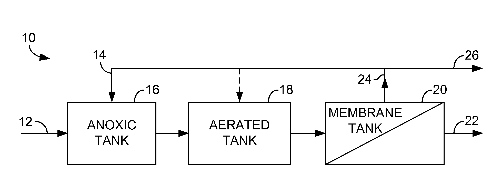
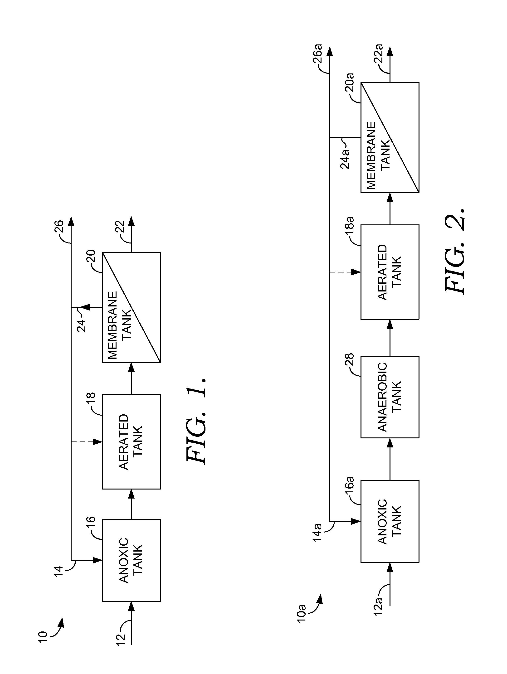
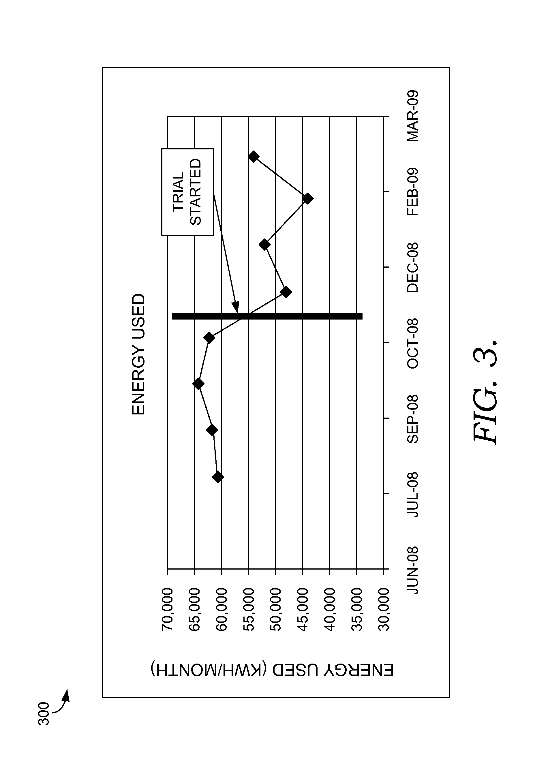
The following example illustrates a plant that has two parallel trains, including a first train (train A) and a second train (train B). The tanks in each trains are identical and are in the same location. The conditions in the tanks, however, are different. Train A represents a typical process that would occur without the user of embodiments of the present invention, while train B represents a process that uses embodiments of the present invention, such as a low dissolved oxygen concentration in the aerated tank, as previously discussed. For example, as shown below in Table 1, the dissolved oxygen concentration in the aerated tank of train A is 1.3 mg / l, while the dissolved oxygen concentration in the aerated tank of train B is 0.1 mg / l. As shown by the levels of phosphorus and nitrate / nitrite removal, in train B compared with those of train A, the lower levels of dissolved oxygen in the aerated tank allow for the development of the phosphorus-removal bacteria in the aerated tank. T...


PUM


Abstract

Methods and systems are provided for reducing ammonia partially by a denitrification process. A stream containing ammonia is contacted with oxygen to form a first product stream in low dissolved oxygen conditions. The ratio of oxygen to nitrogen is about 2.28 g O2/g N—NH3 (2.28 grams of oxygen per gram of nitrogen in ammonia) or less. The first product stream is then exposed to organic matter in an amount of 0.57 g COD/g N—NH3 (0.57 grams of chemical oxygen demand per gram of nitrogen in ammonia). This microbial reaction ultimately produces nitrogen gas, water, and carbon dioxide.

Description

BACKGROUNDRemoving various components from wastewater, such as nitrogen, carbon, and phosphorus can be a difficult and high-cost process that in some instances may require the addition of a carbon source to wastewater treatment process. Additionally, a high concentration of dissolved oxygen used in many wastewater treatment processes contributes substantially to the cost of energy usage of a wastewater treatment plant. A carbon source, such as methanol, may be added to the process in an anoxic tank, for example, to assist with nitrification and denitrification. Further, an aerated tank may require high concentrations of dissolved oxygen to promote oxidation of biological oxygen demand (BOD) and ammonia. The addition of a carbon source and the requirement of high concentrations of dissolved oxygen, however, are costly and significantly contribute to the expense of treating wastewater.SUMMARYEmbodiments of the invention are defined by the claims below, not this summary. A high-level o...

Claims


Application Information

Patent Timeline
IPC IPC(8): C02F3/30
CPCC02F3/1268C02F3/1273C02F3/302C02F3/308C02F2101/105C02F2101/16C02F3/1215Y10S210/906C02F3/2846C02F3/307C02F3/28Y02W10/10C02F3/30C02F3/34
Inventor GIRALDO, EUGENIOLIU, YANJINMUTHUKRISHNAN, SWARNA
Owner AMERICAN WATER WORKS
Why Eureka
Try Eureka