Vehicle control device

a technology of vehicle control and control device, which is applied in the direction of cycle equipment, instruments, transportation and packaging, etc., can solve the problems of uneconomical tire wear, inability to obtain sufficient turning performance, and increase the temperature of the tread end portion, so as to improve acceleration performance and brake performance, and high grip performance

Inactive Publication Date: 2011-09-06
EQUOS RES
View PDF15 Cites 0 Cited by
  • Summary
  • Abstract
  • Description
  • Claims
  • Application Information

AI Technical Summary

Benefits of technology

[0022]With the vehicle control device according to the second aspect, in addition to the advantageous effects of the vehicle control device according to the first aspect, there is an effect that the acceleration performance and the brake performance can be improved by using the first tread having the high grip performance, because the ground contact pressure on the first tread can at least be increased by the low-speed-time activation control unit activating the camber angle adjustment device to adjust the camber angle of the wheel in the case where the ground speed determination unit determines that the ground speed of the vehicle is lower than or equal to the predetermined speed.
[0023]Specifically, the ground speed being less than or equal to a predetermined value shows that there is a high possibility of the vehicle then decelerating to stop or accelerating. Thus, in such cases, it is necessary to ensure the grip force or the stopping force of the vehicle (wheel) in advance.
[0024]With this aspect of the present invention, in the case where the ground speed of the vehicle has become less than or equal to the predetermined value in such situations, the grip force of the wheel can be ensured to improve the acceleration performance and the brake performance by at least increasing the ground contact pressure on the first tread to leverage the high grip performance of the first tread. Note that the adjustment of the camber angle by the low-speed-time activation control unit in this case may be performed such that the ground contact pressure on the first tread becomes larger than the ground contact pressure on the second tread.
[0025]After the vehicle is stopped, the stopping force of the vehicle (wheel) can be ensured by leveraging the high grip performance of the first tread. Accordingly, the vehicle can be stopped in a stable state. Further, in the case of restarting after the stop, the ground contact pressure on the first tread being increased in advance prevents the wheel from slipping, whereby the vehicle can be restarted smoothly and promptly.
[0026]On the other hand, in the case where the ground speed determination unit does not determine that the ground speed of the vehicle is less than or equal to the predetermined value, the driving force or the brake force applied to the vehicle (wheel) is relatively smaller compared to the case described above. In such a case, with this aspect of the present invention, the ground contact pressure on the second tread can be increased (that is, the ground contact pressure on the first tread can be decreased) by activating the camber angle adjustment device to adjust the camber angle of the wheel. Accordingly, fuel saving driving can be realized by using the second tread having the low rolling resistance. Note that the adjustment of the camber angle by the low-speed-time activation control unit in this case may be performed such that the ground contact pressure on the second tread becomes larger than the ground contact pressure on the first tread.
[0027]In this manner, with this aspect, there is an effect that the compatibility can be provided between the two performances of acceleration / deceleration and fuel saving which conflict with each other by the activation control unit (low-speed-time activation control unit) adjusting the camber angle of the wheel to change the ratio of the ground contact pressure on the first tread and the ground contact pressure on the second tread (including the state where only one tread contacts the ground and the other tread does not contact the road surface).

Problems solved by technology

This is because, when the camber angle is set to 0° for example, a tread contacts the ground in the entire region in the width direction during straight-ahead driving, while the tread on the inside is caused to float from the ground by the inclination of the vehicle due to the centrifugal force at the time of turning whereby a sufficient turning performance cannot be obtained.
However, although the turning performance of the tire is improved when the wheel is mounted to the vehicle at a large camber angle in the minus direction, the ground contact pressure on a tread end portion on the inside during the straight-ahead driving is increased whereby there has been a problem that the tire is worn uneconomically and the temperature in the tread end portion increases.
However, in the former technology, there has been a problem that the compatibility between high grip performance and fuel efficiency (low rolling resistance) has been insufficient, although sufficient performance can be obtained in maintaining the high grip performance at the time of turning.
In the related-art technology described above, the high grip performance is limited to the time of turning, and there has been a problem that the high grip performance cannot be sufficiently obtained at a sudden acceleration or a sudden brake during the straight-ahead driving, for example.
In the same manner, in the latter technology, there has been a problem that the compatibility between the high grip performance and fuel efficiency is insufficient.

Method used


Image

  • Vehicle control device
  • Vehicle control device
  • Vehicle control device

Examples


first embodiment

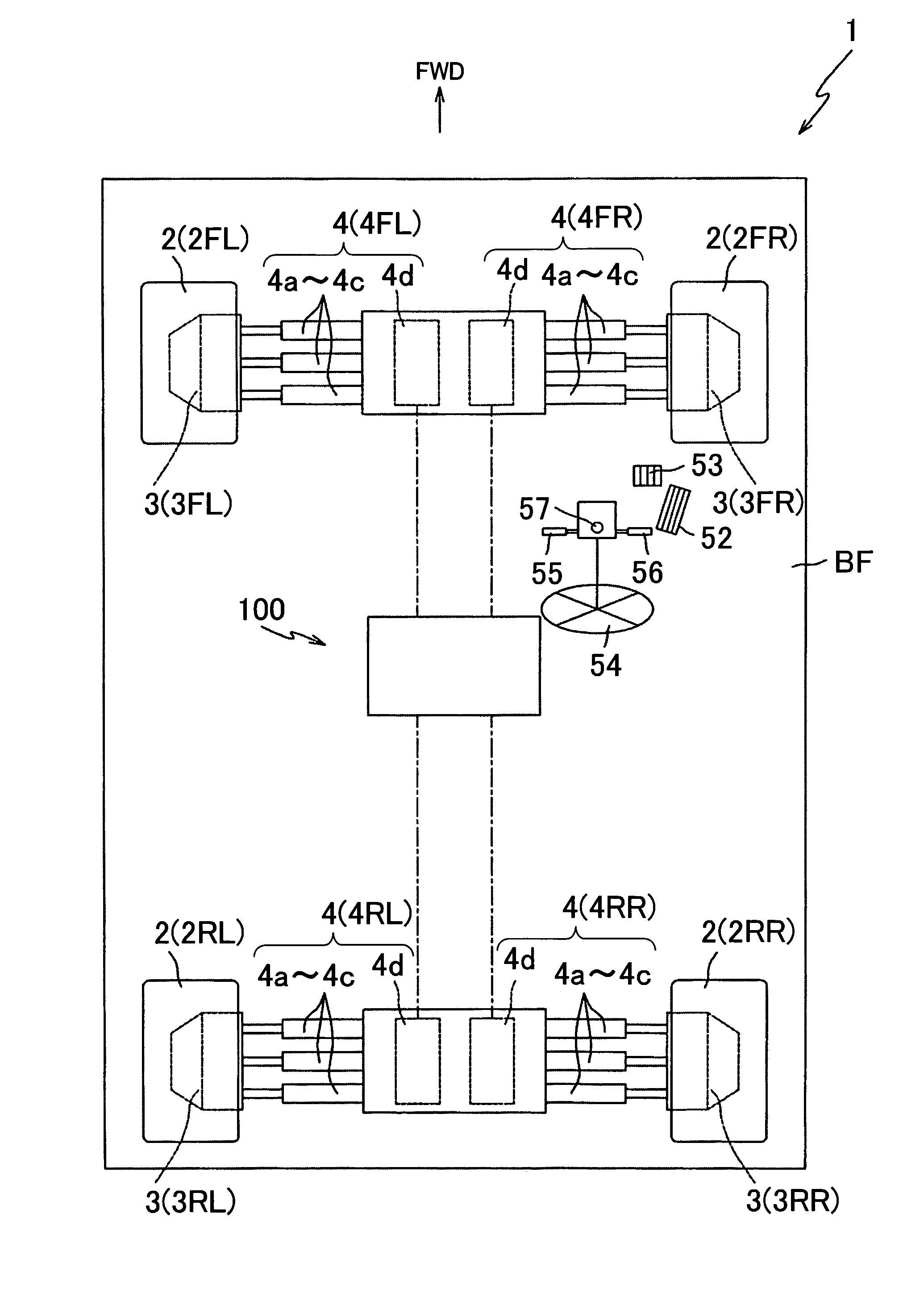
[0050]Hereinafter, preferred embodiments of the present invention will be described with reference to the accompanying drawings. FIG. 1 is a schematic view showing a vehicle 1 in which a vehicle control device 100 according to the present invention is mounted. Note that an arrow FWD in FIG. 1 shows a forward direction of the vehicle 1.

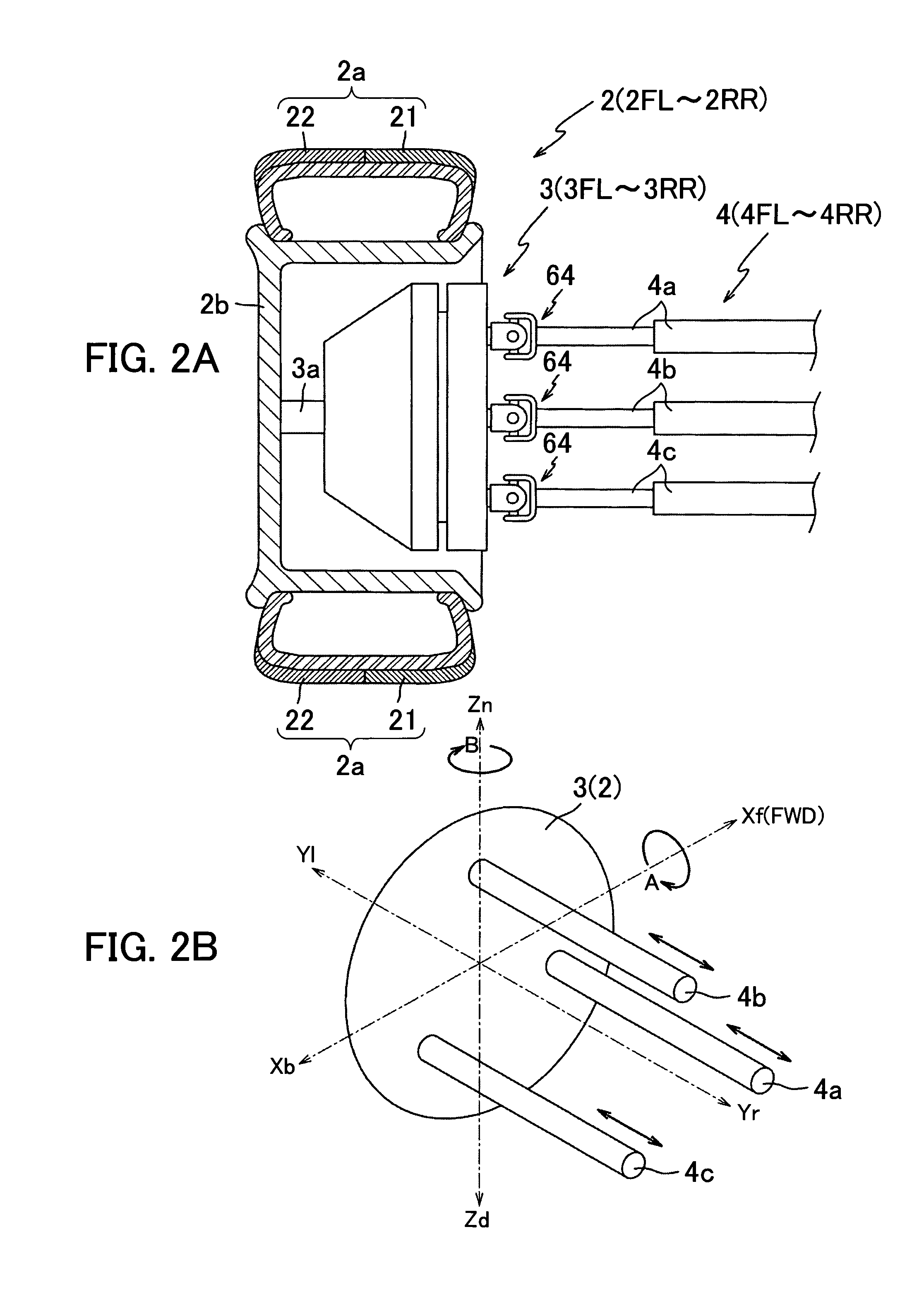
[0051]First, the schematic configuration of the vehicle 1 will be described. As shown in FIG. 1, the vehicle 1 mainly includes a body frame BF, a plurality of (four in this embodiment) wheels 2 supported by the body frame BF, a wheel drive device 3 which rotatably drives each wheel 2 independently, and a camber angle adjustment device 4 which performs steering drive, adjustment of a camber angle, and the like of each wheel 2. The vehicle 1 is configured to achieve an improvement in driving performance and fuel saving by controlling the camber angle of the wheel 2 by the vehicle control device 100 and distinctly using two types of treads provided on the...

second embodiment

[0133]As shown in FIGS. 8 and 9, the wheel 202 of the second embodiment includes the first tread 221 arranged on the inside of the vehicle 201 (right side in FIG. 8) and the second tread 22 having a different characteristic from the first tread 221 and arranged on the outside of the vehicle 201 (left side in FIG. 8).

[0134]Note that the first tread 221 is configured to have a characteristic of a higher grip force (higher grip performance) compared to the second tread 22, and the second tread 22 is configured to have a characteristic of a smaller rolling resistance (lower rolling resistance) compared to the first tread 221.

[0135]As shown in FIGS. 8 and 9, although the wheel 202 is configured such that the width dimensions (dimensions in the horizontal direction in FIG. 8) of the two treads 221 and 22 are the same, the second tread 22 is configured to have an outer diameter approximately constant in the width direction (horizontal direction in FIG. 8) while the first tread 221 is confi...

third embodiment

[0151]As shown in FIG. 12, the wheel 302 of the third embodiment includes the third tread 323, and the first tread 221 is arranged on the inside of the vehicle 301 (right side in FIG. 12), the third tread 323 is arranged on the outside of the vehicle 301 (left side in FIG. 12), and the second tread 22 is arranged between the first tread 221 and the third tread 323.

[0152]The third tread 323 is configured to have a characteristic of a higher grip force at least compared to the second tread 22, and the third tread 323 is configured such that the diameter gradually decreases from the second tread 22 side (right side in FIG. 12) toward the outside of the vehicle 301 (left side in FIG. 12), as shown in FIG. 12.

[0153]Accordingly, only the second tread 22 can be caused to contact the ground in a state where the first tread 221 and the third tread 323 are apart from the road surface G without providing a large camber angle to the wheel 302 (for example, even if the camber angle is set to 0°)...


PUM


Abstract

A vehicle control device and a vehicle are provided with compatibility between high grip performance and fuel efficiency. When a camber angle of a wheel is adjusted as a negative camber, the ground contact pressure on a first tread is increased and the ground contact pressure on a second tread is decreased, thus providing the high grip performance. On the other hand, when the camber angle of the wheel is adjusted as a positive camber, the ground contact pressure on the first tread is decreased and the ground contact pressure on the second tread is increased, thereby reducing rolling resistance and achieving fuel saving. By adjusting the camber angle of the wheel, compatibility can be provided between high grip performance and fuel saving which otherwise conflict with each other.

Description

INCORPORATION BY REFERENCE[0001]The disclosure of Japanese Patent Application No. 2006-182533 filed on Jun. 30, 2006 and Japanese Patent Application No. 2006-325027 filed Nov. 30, 2006, including the specification, drawings and abstract is incorporated herein by reference in its entirety.BACKGROUND OF THE INVENTION[0002]1. Field of the Invention[0003]The present invention relates to a vehicle control device which activates a camber angle adjustment device to control a camber angle of a wheel for a vehicle including the wheel and the camber angle adjustment device which adjusts the camber angle of the wheel. More particularly, the present invention relates to a vehicle control device which can provide compatibility between high grip performance and fuel efficiency.[0004]2. Description of the Related Art[0005]Attempts have been made to sufficiently bring out the capability of a tire to improve the turning performance by providing a large camber angle (angle formed by the center line o...

Claims


Application Information

Patent Timeline
Patent Type & Authority Patents(United States)
IPC IPC(8): G06F7/00B60C3/06B60C5/00B60C11/00B60G17/015B60G17/016B62D7/08
CPCB60C3/06B60C11/0058B60G3/01B60G7/006B60G17/015B60G17/016B60C19/001B60G2200/144B60G2200/46B60G2200/462B60G2202/413B60G2204/414B60G2206/1116B60G2400/106B60G2400/204B60G2400/208B60G2400/34B60G2400/39B60G2400/41B60G2400/822B60G2800/21Y02T10/86
Inventor SAKAKIBARA, FUMIHIKOANDO, MASAOMIKI, NOBUAKISHIRAI, HISANORIHORIGUCHI, MUNEHISAMIZUNO, AKIRA
Owner EQUOS RES
Why Eureka
Try Eureka