
Combination mortise and tenon jig

a tenon jig and combination technology, applied in the field of jigs, can solve the problems of relatively expensive access to such machines, and achieve the effect of quick and relatively easy parts making

Inactive Publication Date: 2011-09-13
GEN TOOLS & INSTR
View PDF21 Cites 11 Cited by
  • Summary
  • Abstract
  • Description
  • Claims
  • Application Information

AI Technical Summary

Benefits of technology

[0004]The present invention is a jig that enables the hobbyist and craftsman to quickly and relatively easily make the parts for a mortise and tenon joint with a router without the need to go through most of the previously described measuring, chiseling and sawing operations. The invention provides for accurately making both the mortise and tenon parts of the joint using the same jig.
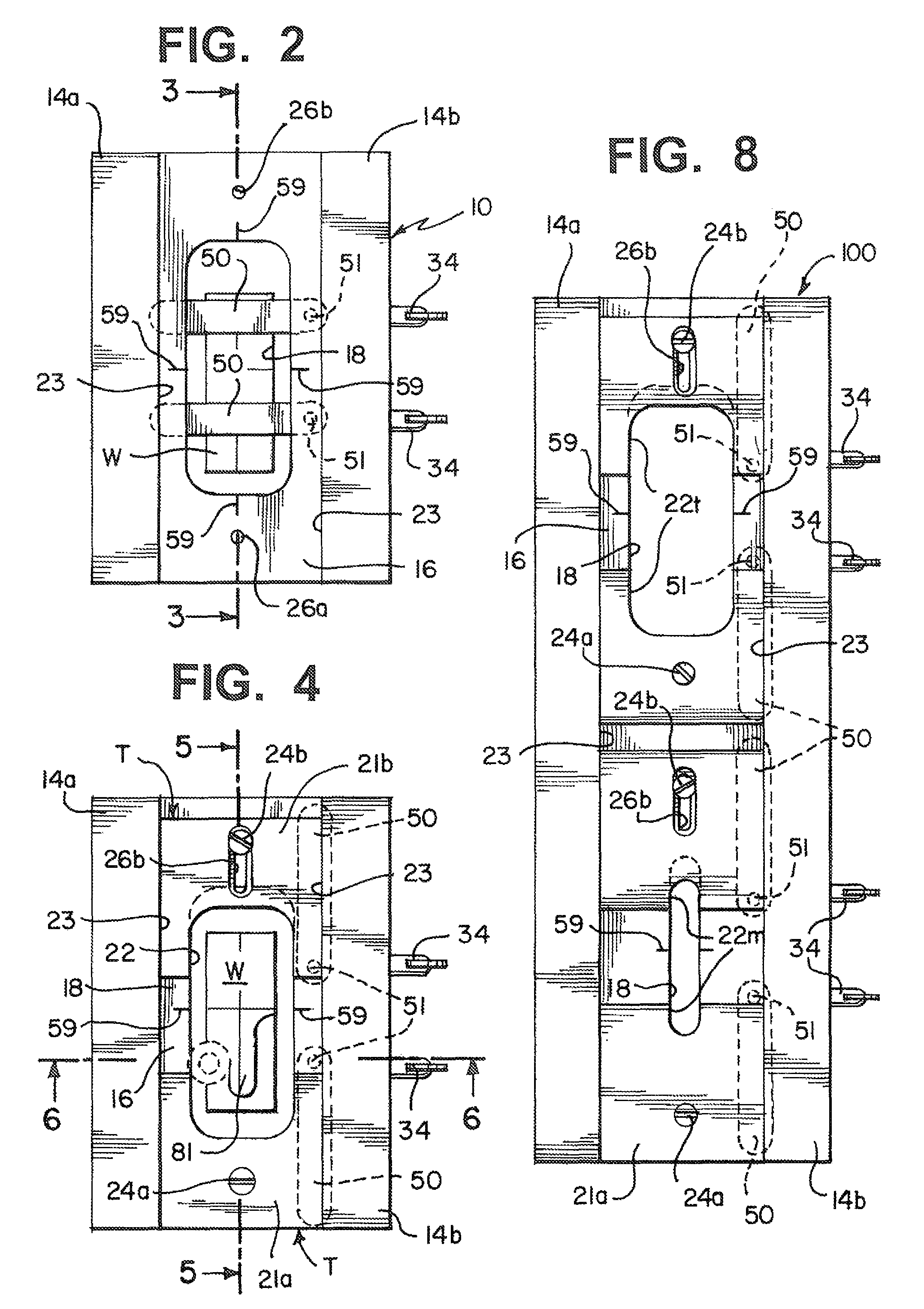
[0008]A router guide template that has a cutout pattern for the mortise or tenon part to be cut is placed on the platform with the pattern overlying the platform open section. The guide template preferably is made of two pieces with at least one of them being movable along the length of the platform to set the length of the pattern cutout thereby allowing mortises and tenons of different lengths to be made. The center of a mortise or tenon part along its length in the workpiece can be set by eye. But it is preferred that this be more accurately accomplished by making a line transverse across the workpiece that will be registered with a mark on the jig body platform or template to set the center point of the length of the mortise or tenon part.

Problems solved by technology

However, a hobbyist or craftsman of a small woodworking shop has no ready access to such machines which can be relatively expensive.

Method used


Image

  • Combination mortise and tenon jig
  • Combination mortise and tenon jig
  • Combination mortise and tenon jig

Examples


Embodiment Construction

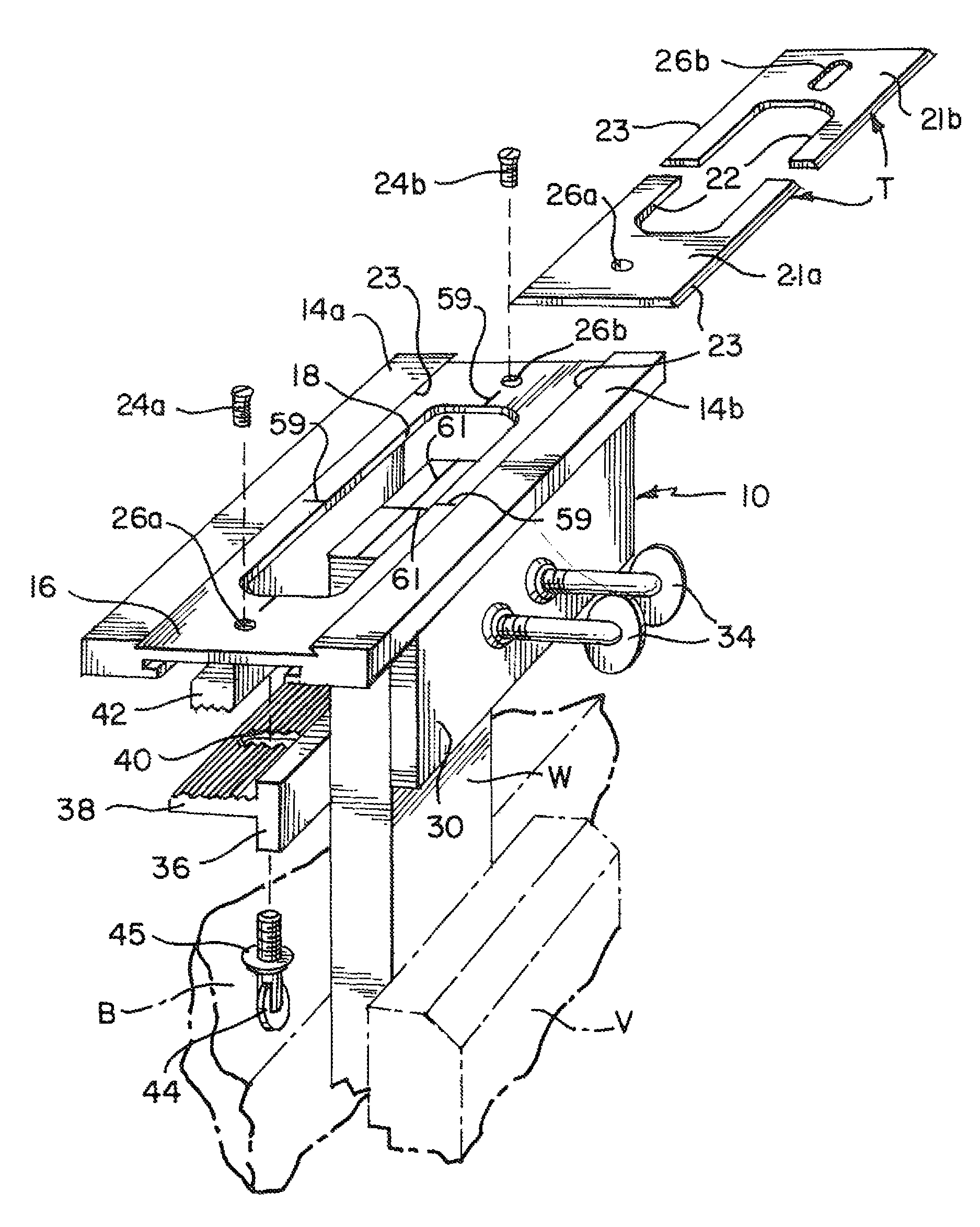
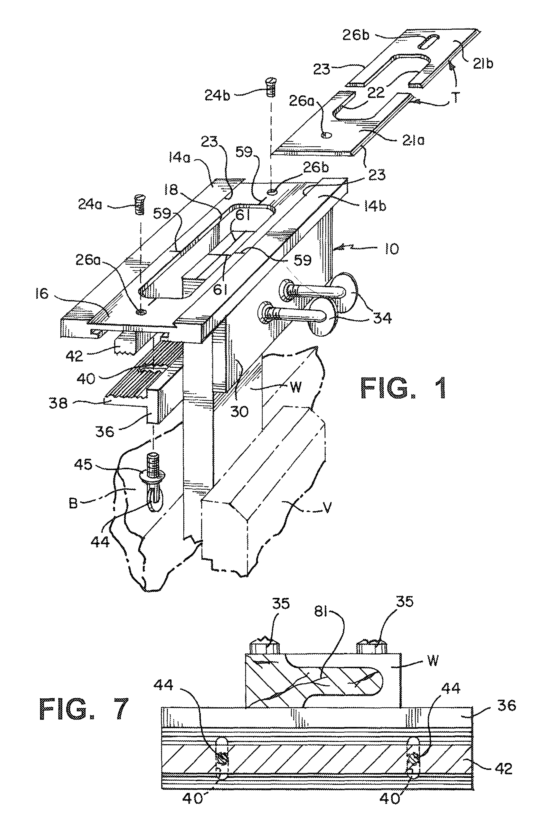
[0019]Referring to FIG. 1, there is a workpiece W in which a mortise or tenon is to be made. In the illustrative example of use of the invention being described, the mortise or tenon is to be cut in the workpiece end. Therefore, the workpiece is vertical with its broad faces across its width below the end held between the inner face of a bench vise V and the edge of a workbench B. The mortise also could be made on a side edge of the workpiece anywhere along its length in which case the workpiece would be held in a horizontal position. A tenon also could be made on the side edge, but it would not be usual. As used in the specification and claims, the terms workpiece “end” or “part” where the mortise and tenon parts are made apply to both vertical and horizontal positioning of the workpiece for making the parts either on the workpiece end or side edge.

[0020]A jig 10 has a body of an upper top part of two outer rails 14a and 14b with flat upper surfaces. Between the rails there is a de...


PUM


Abstract

A combination mortise and tenon jig has a body including a platform having an open section with first and second clamp legs on opposite sides for holding a workpiece therebetween with the workpiece part in which a mortise or tenon is to be cut facing toward the open section. A plurality of adjustable members extend from the first clamp leg to engage a workpiece face and the second clamp leg is movable relative to the open section with the extending members and the second clamp leg holding the workpiece at a selected position in the open section. A pair of guide arms pivotally mounted below the platform swing across the platform open section to engage the workpiece part and make it parallel to the platform and a template having a cutout pattern of one of a mortise or tenon overlies the platform open section to guide a router bit to cut the mortise or tenon in the workpiece end.

Description

FIELD OF THE INVENTION[0001]The present invention is for a jig to produce both the mortise and the tenon parts of a mortise and tenon joint.BACKGROUND OF THE INVENTION[0002]A mortise and tenon joint provides one of the oldest and most useful ways of joining two or more wood pieces in the making of furniture and other wood products. This joint is of two parts. The first part is the “mortise” which is a cavity cut into one wood workpiece. The mortise is of a size and shape to accept the joining “tenon” part, which is a mating projection cut into the end of a second workpiece.[0003]Various types of machines exist to make mortise and tenon joints on a production basis. However, a hobbyist or craftsman of a small woodworking shop has no ready access to such machines which can be relatively expensive. The typical method of making a mortise and tenon joint by hobbyists and craftsmen involves several separate operations and a number of different tools. Making the mortise involves measuring,...

Claims


Application Information

Patent Timeline
IPC IPC(8): B27C5/00
CPCB23Q9/0042B27F1/08B27F5/02B27F5/12
Inventor WEINSTEIN, BURTON
Owner GEN TOOLS & INSTR
Learn More