
Information recording medium, target and method for manufacturing of information recording medium using the same

a technology of information recording medium and target, which is applied in the direction of record information storage, instruments, transportation and packaging, etc., can solve the problems of low erasure rate, difficult to migrate atoms, and absorption distortion, and achieve high crystallization rate, wide linear velocity margin, and high linear velocity

Inactive Publication Date: 2011-09-13
PANASONIC CORP
View PDF13 Cites 2 Cited by
  • Summary
  • Abstract
  • Description
  • Claims
  • Application Information

AI Technical Summary

Benefits of technology

[0012]The present invention is intended to provide an information recording medium that is capable of high-speed recording and has good signal storage stability even when the recording layer is thin. The present invention also is intended to provide, at low cost, an information recording medium that is capable of high-speed recording and has good signal storage stability even when the recording layer is thin, by forming recording layers having desired crystallization rates from limited targets.
[0022]Phase change materials (recording layer materials) to be used for the recording layers of the first and second information recording media of the present invention each have a high crystallization rate and are capable of recording at a high linear velocity even when they are thin. Furthermore, they also allow marks to be formed stably even at a lower linear velocity and have wider linear velocity margins compared to conventional ones. Moreover, they have good signal storage stability.
[0023]Conceivably, the above-mentioned effects can be obtained since the composite contained as a main component in the recording layer contains at least 60% of Sb, which provides the recording layer with high crystallization ability, and further Ge is contained therein, which makes it possible to stabilize amorphous marks. Furthermore, it is conceivable that Te is contained, so that a greater optical variation is obtained and good signal properties of the information recording medium also are obtained.
[0024]Moreover, like the second information recording medium of the present invention, since the recording layer is formed of a plurality of component layers, similar recording properties as described above can be obtained even when it is configured to have a plurality of recording layers (even in the case of a structure with multilayered information layers). Furthermore, even when a plurality of recording layers have different composition ratios from each other, they can be formed using the same target by changing the ratio in thickness of the laminated layers. Therefore, in the second information recording medium of the present invention, it is no longer necessary to prepare targets whose number corresponds to the number of recording layer compositions with respect to one information recording medium, and thus the cost of information recording media can be reduced.
[0025]With the target of the present invention, for example, the first and second information recording media as described above can be manufactured easily.
[0026]Furthermore, the methods of manufacturing the first and second information recording media of the present invention make it possible to manufacture first and second information recording media having effects as described above.

Problems solved by technology

However, when the thickness of the recording layer is reduced, it tends to be difficult for atoms to migrate.
Conceivably, a cause of a low erasure rate is distortion (absorption distortion) of marks that results from the difference in optical absorptance between a crystalline region and an amorphous region.
These differences result in a decrease in erasure rate.
Accordingly, the quality of reproduced signals is deteriorated.
That is, this leads to deterioration in signal storage stability.
Accordingly, the cost for targets is high and additional cost is required.
The additional cost is cost that accompanies an increase in the number of film formation chambers.
Therefore, it is difficult to reduce the cost of the information recording medium.

Method used


Image

  • Information recording medium, target and method for manufacturing of information recording medium using the same
  • Information recording medium, target and method for manufacturing of information recording medium using the same
  • Information recording medium, target and method for manufacturing of information recording medium using the same

Examples


embodiment 1

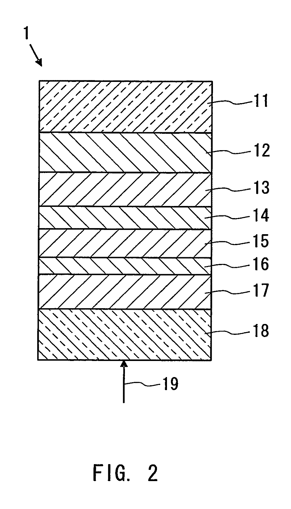
[0095]An example of information recording media that record and reproduce information using a laser beam (an example of the first information recording medium of the present invention) is described as Embodiment 1 of the present invention. FIG. 2 shows a partial cross-sectional view of the optical information recording medium.

[0096]The information recording medium 1 shown in FIG. 2 is formed with a reflective layer 12, a second dielectric layer 13, a second interface layer 14, a recording layer 15, a first interface layer 16, a first dielectric layer 17, and a cover layer 18 that are disposed sequentially on the surface of a substrate 11. This information recording medium 1 is irradiated with an energy beam (generally, a laser beam) 19 for recording and reproduction from the first dielectric layer 17 side.

[0097]The cover layer 18 is formed of, for example, a dielectric or a resin such as a photocurable resin (particularly, an ultraviolet curable resin) or a slow-acting thermosetting...

embodiment 2

[0125]Another example of the information recording medium on or from which information is recorded or reproduced using a laser beam (another example of the first information recording medium of the present invention) is described as Embodiment 2 of the present invention. FIG. 3 shows a partial cross-sectional view of the optical information recording medium.

[0126]The information recording medium 2 shown in FIG. 3 is formed with a reflective layer 12, a second dielectric layer 13, a recording layer 15, a first interface layer 16, a first dielectric layer 17, and a cover layer 18 that are stacked in this order on the surface of a substrate 11. This information recording medium 2 is irradiated with an energy beam (generally, a laser beam) 19 for recording and reproduction from the first dielectric layer 17 side. In the information recording medium 2, the second dielectric layer 13 and the first interface layer 16 are layers (a first adjacent layer and a second adjacent layer) disposed ...

embodiment 3

[0133]Still another example of the information recording medium on or from which information is recorded or reproduced using a laser beam (another example of the first information recording medium of the present invention) is described as Embodiment 3 of the present invention. FIG. 4 shows a partial cross-sectional view of the optical information recording medium. The information recording medium 3 of this embodiment includes N (where N is an integer of 2 or more) information layers for recording and reproducing information. It is a multilayer optical information recording medium in which information can be recorded on or reproduced from each information layer by irradiation with an energy beam (generally, a laser beam) 19 from one side. The information recording medium 3 is provided with a first information layer 31 to an N-th information layer 38 that are stacked sequentially, with, for example, optical separation layers 32, 34, 35, and 37 being interposed therebetween.

[0134]The s...


PUM

PropertyMeasurementUnit
thicknessaaaaaaaaaa
thicknessaaaaaaaaaa
thicknessaaaaaaaaaa

Abstract

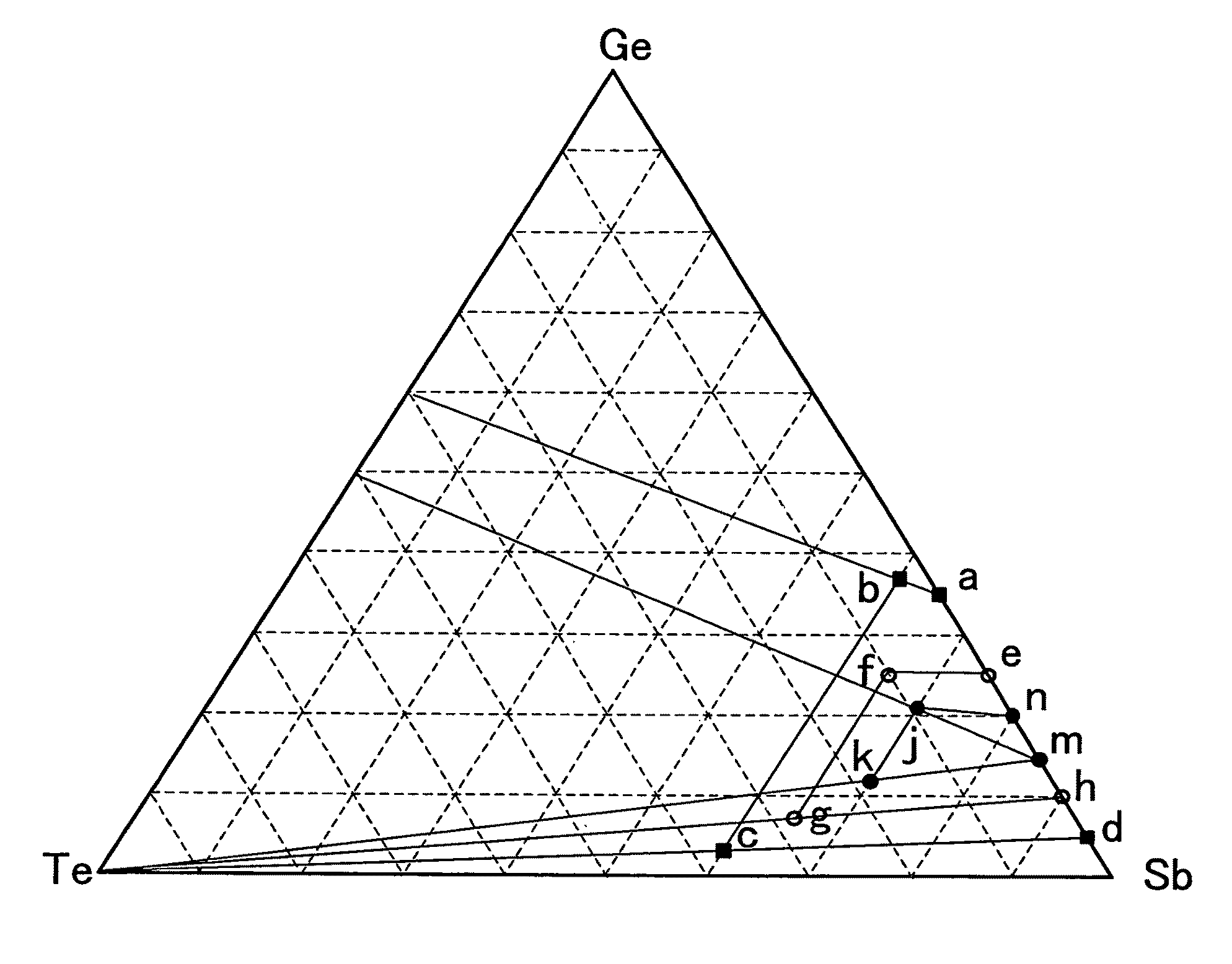
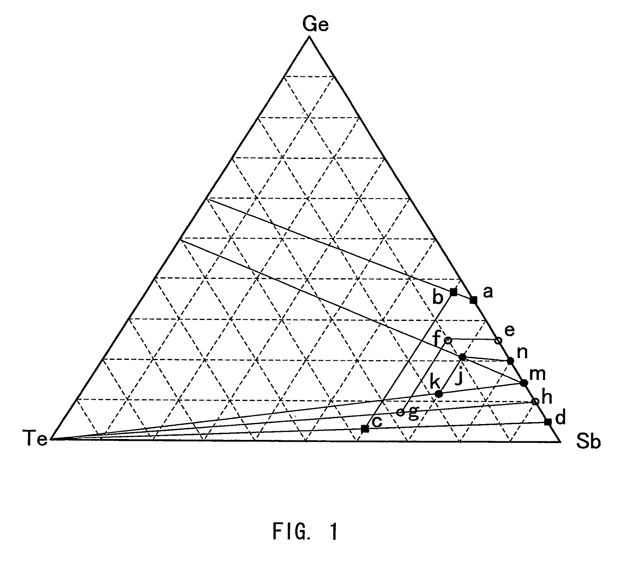
An information recording medium of the present invention includes a recording layer whose phase changes by irradiation with a laser beam or application of current. The recording layer contains, as its main component, a composite composed of Ge and Sb that are essential components, and Te that is an optional component. The composite has a composition within a region enclosed by: point (a) (35, 65, 0), point (b) (36.9, 60, 3.1), point (c) (3.2, 60, 36.8), and point (d) (5, 95, 0) in terms of a coordinate (Ge, Sb, Te)=(x, y, z) on the triangular coordinate shown in FIG. 1, where point (b) corresponds to a point at Sb=60 on Ge60Te40—Ge35Sb65, point (c) corresponds to a point at Sb=60 on Te—Ge5Sb95, and the region includes lines extending between point (a) and point (b), point (b) and point (c), point (c) and point (d), and point (d) and point (a).

Description

BACKGROUND OF THE INVENTION[0001]1. Field of the Invention[0002]The present invention relates to an information recording medium on or from which information is recorded or reproduced by an optical or an electrical system and a method for manufacturing the same as well as a target to be used for the manufacturing method.[0003]2. Related Background Art[0004]An example of optical information recording media is a phase-change information recording medium in which information is recorded, rewritten, or erased optically using a laser beam. The recording, erasure, and rewriting in the phase-change information recording medium are performed through reversible changes of a phase change material between crystalline and amorphous states in a recording layer thereof. Generally, information is recorded by irradiating an information recording medium with a high power laser beam to heat the recording layer to a higher temperature than its melting point so as to melt the irradiated region, and the...

Claims


Application Information

Patent Timeline
Patent Type & Authority Patents(United States)
IPC IPC(8): B32B3/02G11B7/24035G11B7/24038G11B7/243G11B7/2433
CPCC23C14/0623G11B7/24038G11B7/2433H01L45/06H01L45/12H01L45/1233H01L45/144H01L45/148H01L45/1625C23C14/3414Y10T428/21G11B7/2533G11B7/2578G11B7/258G11B11/002G11B2007/24312G11B2007/24314G11B2007/24316G11C13/0004H10N70/231H10N70/801H10N70/826H10N70/8828H10N70/884H10N70/026
Inventor TSUCHINO, AKIOKUSADA, HIDEOKOJIMA, RIEYAMADA, NOBORU
Owner PANASONIC CORP
Learn More