Method and system for fuel vapor control

a technology of fuel vapor and purging system, which is applied in the direction of hybrid vehicles, electrical control, instruments, etc., can solve the problems of insufficient purging of fuel vapor from the vehicle's emission control system, refueling and emission control system leak detection operations that are dependent on pressure and vacuum, and operation may also be affected, so as to reduce the overall carbon emissions of the vehicle, shorten the engine operation time, and reduce the effect of overall carbon emissions

Active Publication Date: 2011-09-13
FORD GLOBAL TECH LLC
View PDF33 Cites 52 Cited by
  • Summary
  • Abstract
  • Description
  • Claims
  • Application Information

AI Technical Summary

Benefits of technology

Hybrid vehicles, such as plug-in hybrid vehicles, may have two modes of operation: an engine-off mode and an engine-on mode. While in the engine-off mode, power to operate the vehicle may be supplied by stored electrical energy. While in the engine-on mode, the vehicle may operate using engine power. By switching between electrical and engine power sources, engine operation times may be reduced, thereby reducing overall carbon emissions from the vehicle. However, shorter engine operation times may lead to insufficient purging of fuel vapors from the vehicle's emission control system. Additionally, refueling and emission control system leak detection operations that are dependent on pressures and vacuums generated during engine operation may also be affected by the shorter engine operation times in hybrid vehicles.
Various strategies have been developed to address fuel vapor control and management in hybrid vehicle systems. Example approaches include separating storage of refueling vapors from storage of diurnal vapors by adding a fuel tank isolation valve (FTIV) between a fuel tank and a fuel vapor retaining canister, and allowing refueling vapors to the canister during refueling events, and engine-on purging methods. The separation of diurnal and refueling vapors allows a pressure to be generated in the fuel tank, while application of alternative vacuum sources allows a vacuum to be generated in the canister.
In this way, by adjusting an order of application of vacuum and / or pressure on fuel vapor recovery system components based on availability of vacuum and / or pressure, leak detection may be performed on all the components of the system even when the duration of the engine-on operation varies in the hybrid vehicle. Additionally, leak detection in the components may be decoupled from each other based on the amount of pressure and / or vacuum available. By decoupling leak detection in a first component, such as the fuel tank, from leak detection in a second component, such as the canister, a more robust leak detection routine may be possible.

Problems solved by technology

However, shorter engine operation times may lead to insufficient purging of fuel vapors from the vehicle's emission control system.
Additionally, refueling and emission control system leak detection operations that are dependent on pressures and vacuums generated during engine operation may also be affected by the shorter engine operation times in hybrid vehicles.
However, the inventors herein have recognized potential issues with these approaches.
As one example, these approaches fail to address the transitory nature of pressure and vacuum accumulation in a hybrid vehicle system due to infrequent and irregular engine operation.
For example, the shorter duration of engine operation in hybrid vehicles may lead to lower amounts of vacuum being generated during an engine-on mode, such that insufficient vacuum may be present in the fuel tank for a subsequent leak detection operation.
As a result, there may not be sufficient pressure and / or vacuum for detecting leaks in both the fuel tank and the carbon canister.
Since leak detection in the fuel tank in the above approaches is tied to leak detection in the carbon canister, insufficient pressure and / or vacuum may lead to incomplete fuel vapor recovery system leak detection.
Also, operation of an external dedicated pump to generate vacuum and / or pressure for leak detection may increase system cost and power consumption.

Method used


Image

  • Method and system for fuel vapor control
  • Method and system for fuel vapor control
  • Method and system for fuel vapor control

Examples


Embodiment Construction

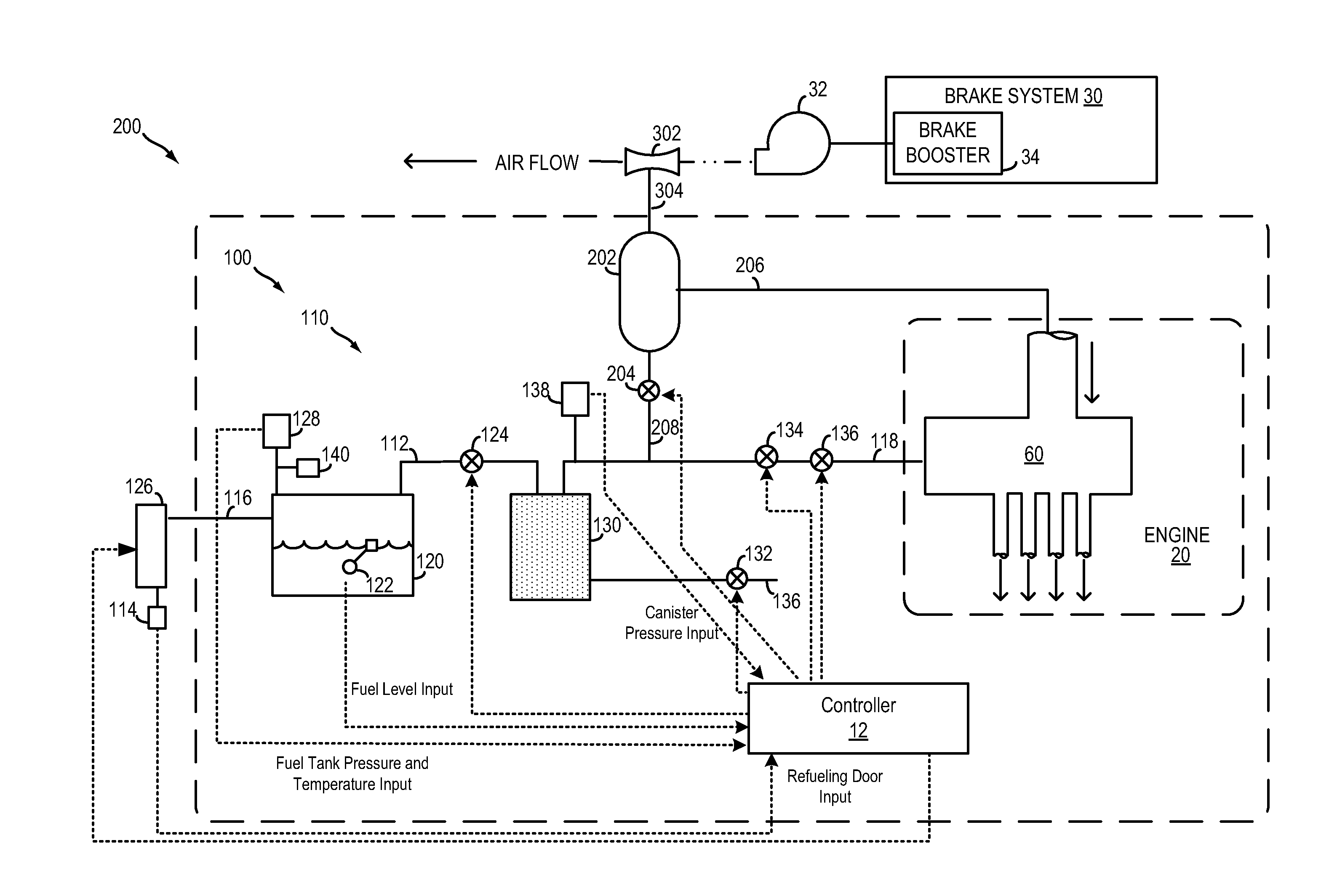
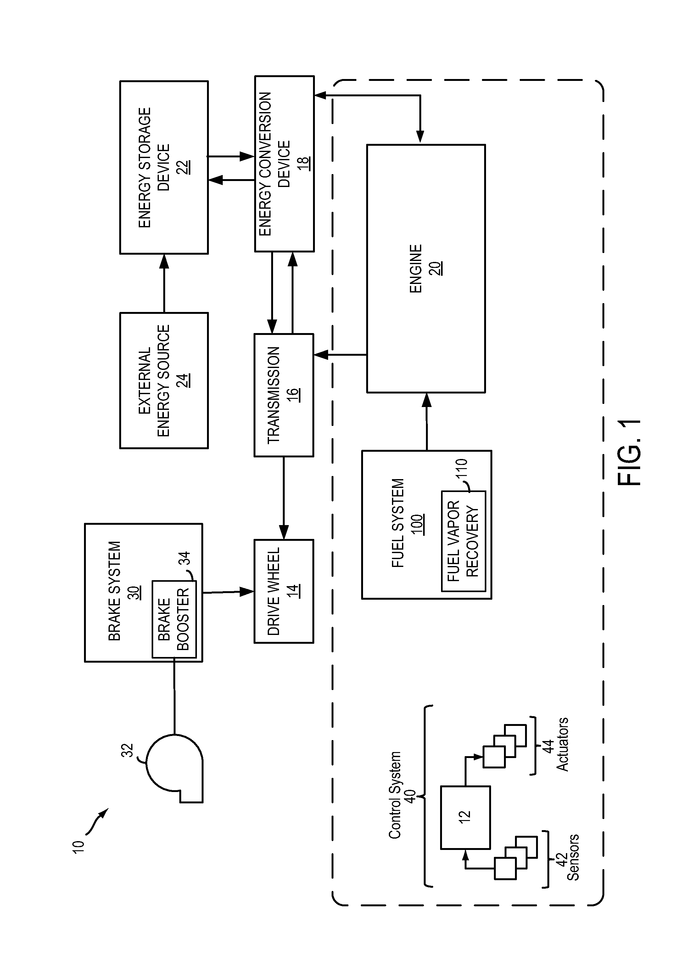
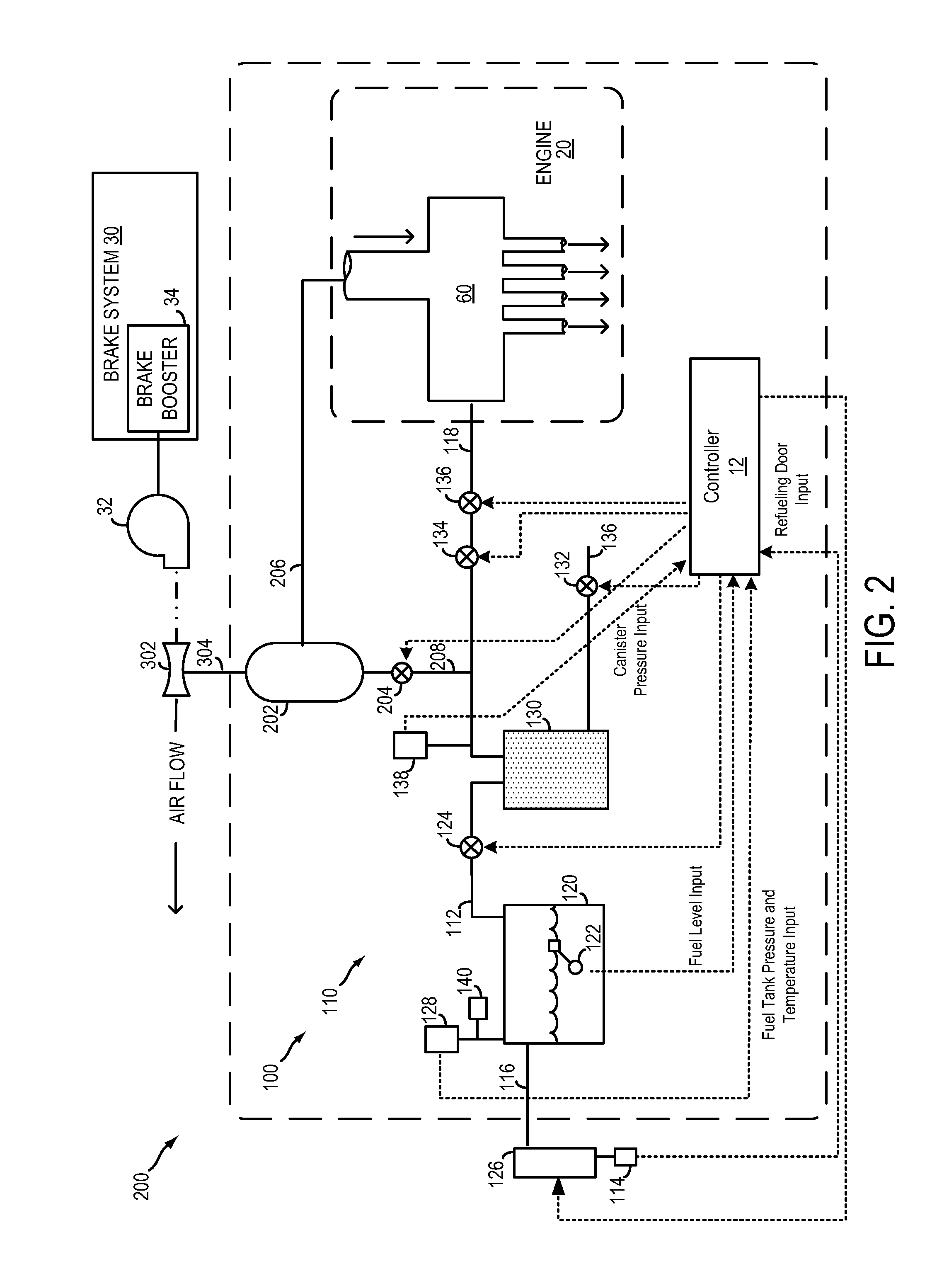
The following description relates to a fuel vapor recovery system for a hybrid vehicle, such as the vehicle system of FIG. 1, and a method of monitoring flow of fuel vapors and / or air though the fuel vapor recovery system. As shown in FIG. 2, the fuel vapor recovery system may include a fuel tank isolated from a canister by a fuel tank isolation valve (FTIV), the canister further coupled to an engine intake by a canister purge valve (CPV). In this way, refueling vapors may be stored in the canister while diurnal vapors are retained in the fuel tank, dividing the fuel vapor circuit into a canister side and a fuel tank side. A vacuum accumulator may be included in the fuel vapor recovery system to provide a vacuum source to the canister. The vacuum accumulator may be configured to generate and store vacuum during engine-on conditions and engine-off conditions, such as from the engine and / or from a brake booster pump. A controller may receive signals from various sensors including pres...


PUM

PropertyMeasurementUnit
thresholdaaaaaaaaaa
pressureaaaaaaaaaa
vacuumaaaaaaaaaa

Abstract

A method and system for fuel vapor control in a hybrid vehicle (HEV). The HEV fuel vapor recovery system includes a fuel tank isolation valve, which is normally closed to isolate storage of refueling from storage of diurnal vapors. The method for fuel vapor control includes selectively actuating the fuel tank isolation valve during interrelated routines for refueling, fuel vapor purging, and emission system leak detection diagnostics to improve regulation of pressure and vacuum the HEV fuel vapor recovery system.

Description

FIELDThe present application relates to fuel vapor purging in a hybrid vehicle.BACKGROUND AND SUMMARYHybrid vehicles, such as plug-in hybrid vehicles, may have two modes of operation: an engine-off mode and an engine-on mode. While in the engine-off mode, power to operate the vehicle may be supplied by stored electrical energy. While in the engine-on mode, the vehicle may operate using engine power. By switching between electrical and engine power sources, engine operation times may be reduced, thereby reducing overall carbon emissions from the vehicle. However, shorter engine operation times may lead to insufficient purging of fuel vapors from the vehicle's emission control system. Additionally, refueling and emission control system leak detection operations that are dependent on pressures and vacuums generated during engine operation may also be affected by the shorter engine operation times in hybrid vehicles.Various strategies have been developed to address fuel vapor control an...

Claims


Application Information

Patent Timeline
Patent Type & Authority Patents(United States)
IPC IPC(8): F02M37/04G01L3/26G06F19/00
CPCB60K15/03504F02D29/02F02D41/003F02D41/021F02M25/0818F02M35/10229B60W2560/00F02D41/0032F02D41/221Y02T10/6269B60W2530/00Y02T10/62
Inventor DEBASTOS, TIMOTHYKACEWICZ, JOHN MICHAELBOHR, SCOTTPEARCE, RUSSELL RANDALLKRAGH, CHRISTOPHERSULLIVAN, PATRICKEULISS, WILLIAMKLUZNER, MICHAEL IGOR
Owner FORD GLOBAL TECH LLC
Why Eureka
Try Eureka