
Method and apparatus for setting a dynamically adjustable position of an imaging system

a dynamic adjustment and imaging system technology, applied in the field of angiography systems, can solve the problems of unfavorable method and introduction of real-time fluoroscopy images, and achieve the effect of precise positioning and increased accuracy and reliability of interventional operations

Active Publication Date: 2011-09-20
SIEMENS HEALTHCARE GMBH
View PDF8 Cites 1 Cited by
  • Summary
  • Abstract
  • Description
  • Claims
  • Application Information

AI Technical Summary

Benefits of technology

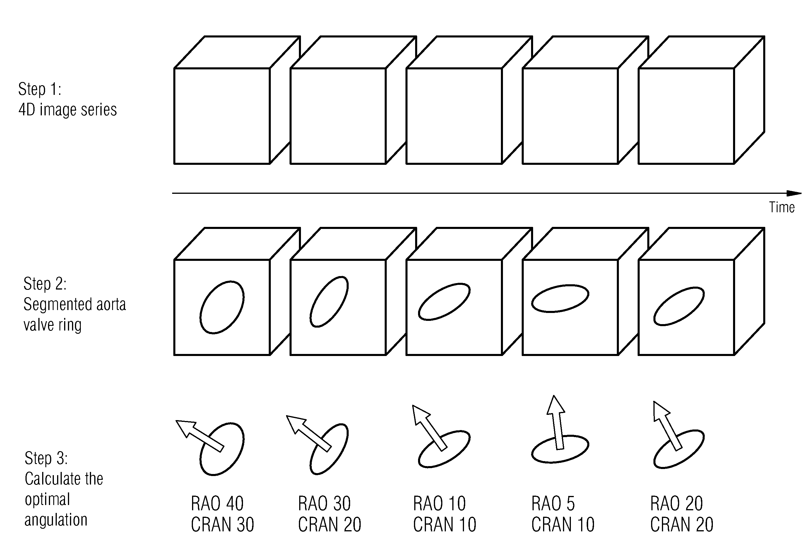
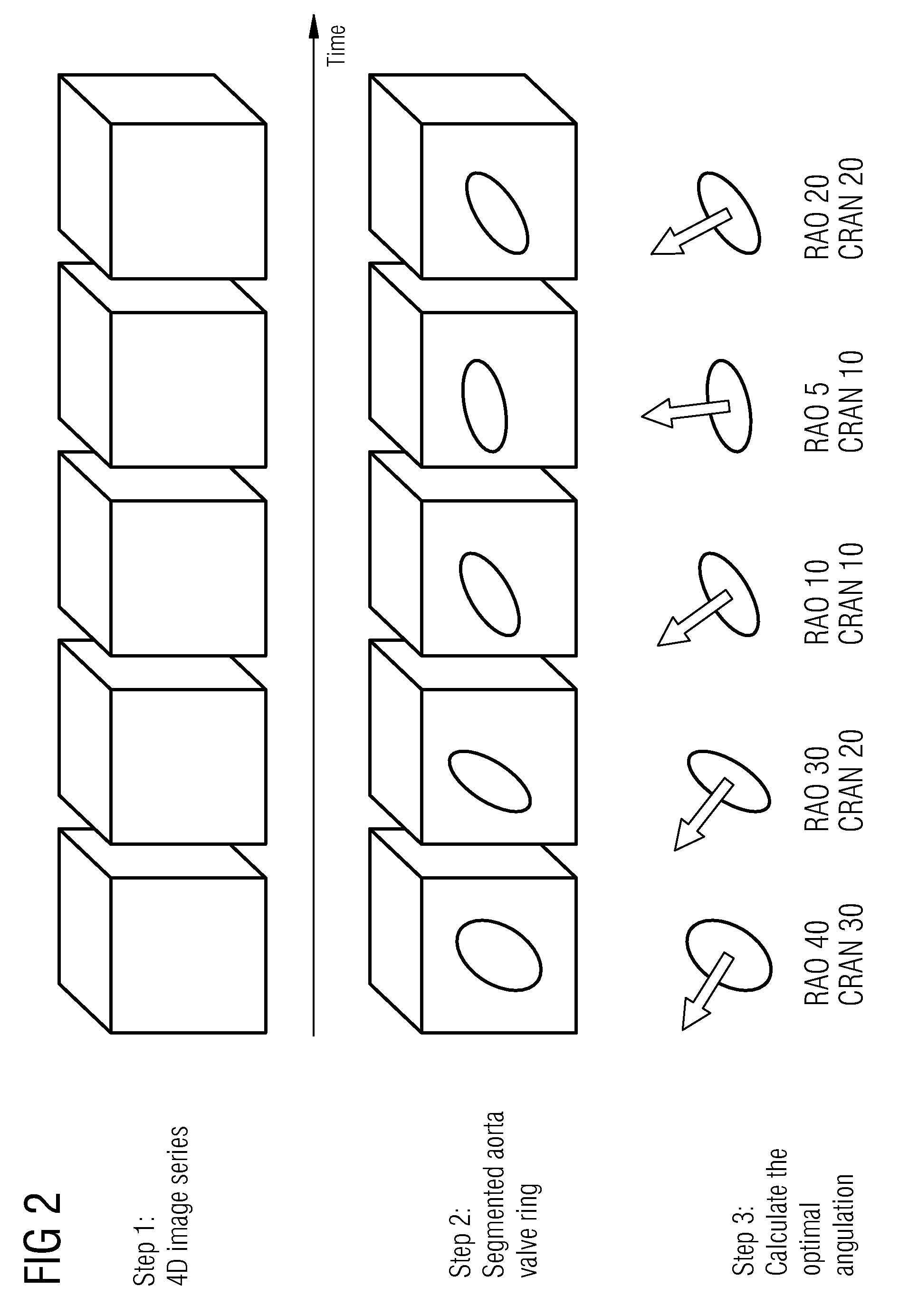
[0025]The inventive procedure can also be used in other instances in which organ movement plays a role, for instance an adjustment of the C-arm to the breathing movement in the case of interventions in lungs or the abdomen. The inventive procedure can be extended such that account can be easily taken of both the breathing and heart movements (in this case 5D data records are generated). This could increase the accuracy and reliability of the interventional operation, particularly in instances in which a very precise positioning of a heart valve is necessary.

Problems solved by technology

One problem with the use of 3D or 4D volume data during the intervention is the introduction of real-time fluoroscopy images in conjunction with the volume data.
This method is unfavorable particularly with structures which implement the complex movements, like for instance the aorta valve.

Method used


Image

  • Method and apparatus for setting a dynamically adjustable position of an imaging system
  • Method and apparatus for setting a dynamically adjustable position of an imaging system
  • Method and apparatus for setting a dynamically adjustable position of an imaging system

Examples


Embodiment Construction

[0030]FIG. 3 shows a C-arm x-ray system 1 for instance which has a rotatably mounted C-arm 2, to the ends of which are attached an x-ray radiation source, for instance an x-ray emitter 3 and an x-ray image detector 4. The x-ray image detector 4 may be a rectangular or square flat semi-conductor detector, which is preferably manufactured from amorphous silicon. A patient support table 5 for accommodating a structure of interest, for instance a moving object, e.g. heart or lung of a patient 9, is located in the radiation path of the radiation source 3. An image system 6 is connected to the x-ray system, said image system receiving and processing the image signals of the x-ray detector 4. The image system 6 also includes an evaluation computer 7 and a reproduction apparatus 8, preferably embodied as a dual-monitor System.

[0031]The rotatably mounted C-arm 2 comprising x-ray emitter 3 and image detector 4 is rotated in order to generate 3D image data records. The x-ray radiation source 3...


PUM

PropertyMeasurementUnit
structureaaaaaaaaaa
timeaaaaaaaaaa
time-aaaaaaaaaa

Abstract

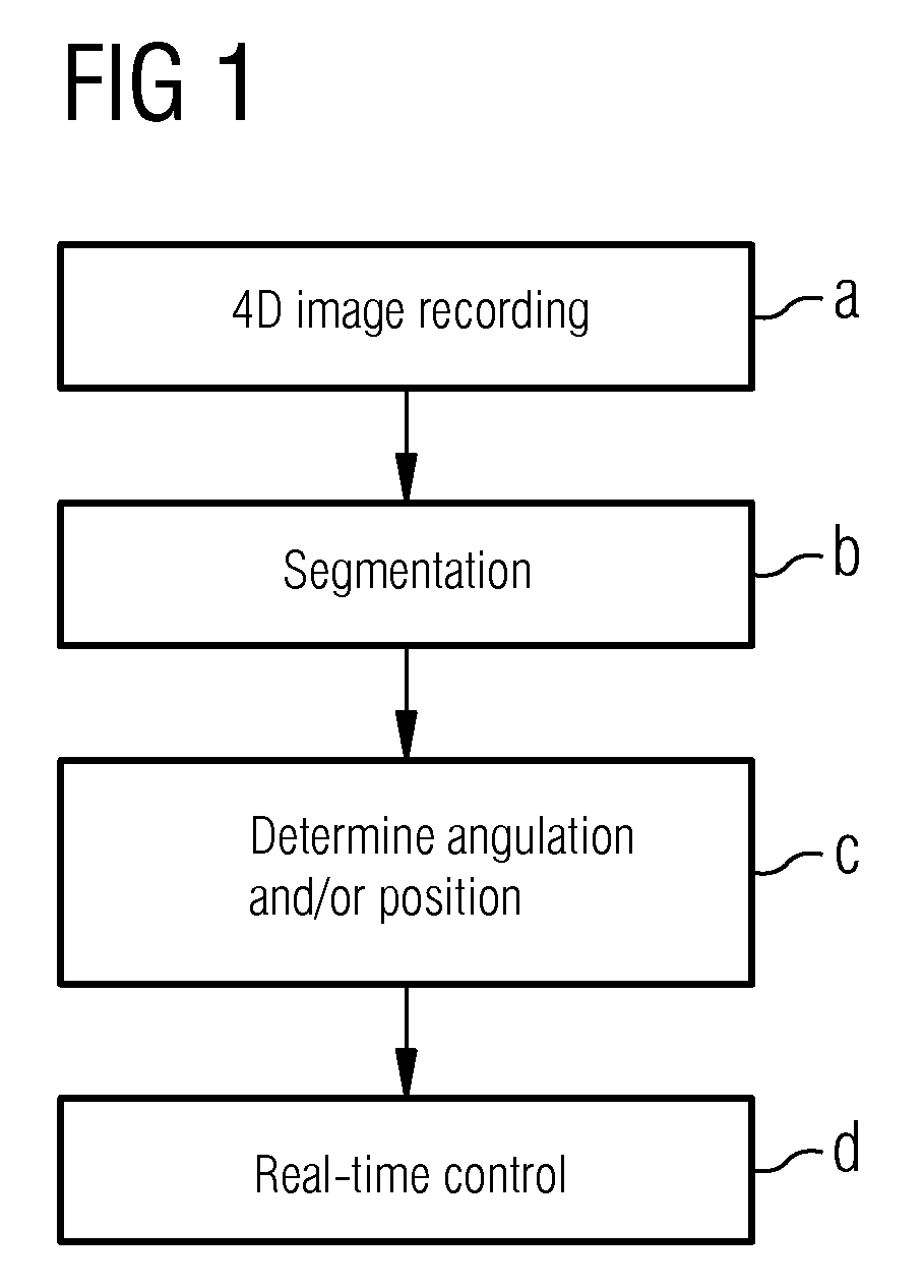
The invention relates to a method and an apparatus for setting a dynamically adjustable position of an imaging system for providing an optimum view onto a moving object during a medical intervention. A time-resolved at least three-dimensional data record of the moving object is generated. A position of the imaging system for each period of time is determined from the time-resolved data record from which the optimum view onto a structure of interest of the moving object is produced and automatically setting a calculated position of the imaging system in real-time so that the optimum view onto the structure of interest can be shown at any time. Optionally prior to determining the position of the imaging system, a structure of interest of the moving object can be segmented with this structure being segmented for each period of time from the time-resolved data record.

Description

CROSS REFERENCE TO RELATED APPLICATIONS[0001]This application claims priority of German application No. 10 2008 033 137.6 filed Jul. 15, 2008, which is incorporated by reference herein in its entirety.FIELD OF THE INVENTION[0002]The invention relates to a method and an apparatus for setting a dynamically adjustable position of an imaging system for providing at least one optimum view onto a moving object preferably during a medical intervention.BACKGROUND OF THE INVENTION[0003]The invention preferably relates to angiography systems, which are used for interventional operations on the heart for instance. Such angiography systems are generally represented by C-arm x-ray devices. It is possible to generate three-dimensional (3D) or even four-dimensional (4D corresponds to 3D plus time) image data using angiography systems, like is known for instance from DE 10 2004 048 209 B3.[0004]One problem with the use of 3D or 4D volume data during the intervention is the introduction of real-time...

Claims


Application Information

Patent Timeline
Patent Type & Authority Patents(United States)
IPC IPC(8): G01N23/00H05G1/62
CPCA61B6/504A61B6/4441
Inventor BOESE, JAN
Owner SIEMENS HEALTHCARE GMBH
Learn More