
Optical band splitter/combiner device comprising a three-arms interferometer

a three-arms, splitter technology, applied in the direction of optical elements, multiplex communication, instruments, etc., can solve the problems of disadvantageous device compactness, high power requirement in the wavelength band of 155010 nm, and the replacement of two 3db directional couplers with two mz interferometers, etc., to achieve strong tolerance to fabrication errors, reduce alignment problems, and increase automation

Inactive Publication Date: 2011-09-20
GOOGLE LLC
View PDF7 Cites 9 Cited by
  • Summary
  • Abstract
  • Description
  • Claims
  • Application Information

AI Technical Summary

Benefits of technology

[0033]The applicant faced the problem of providing an optical band splitter / combiner device capable of effectively splitting / combining two wide optical wavelength bands having central wavelengths widely spaced.

Problems solved by technology

In order to provide a high-quality analog television service, power requirement in the wavelength band of 1550±10 nm is typically greatly demanding.
In FTTP networks, as well in many other applications, a key issue is signal splitting and / or combining which allows the downstream and upstream signals to be suitably combined and / or splitted.
However, the Applicant notes that the replacement of the two 3 dB directional couplers with two MZ interferometers is disadvantageous for the compactness of the device.

Method used


Image

  • Optical band splitter/combiner device comprising a three-arms interferometer
  • Optical band splitter/combiner device comprising a three-arms interferometer
  • Optical band splitter/combiner device comprising a three-arms interferometer

Examples


Embodiment Construction

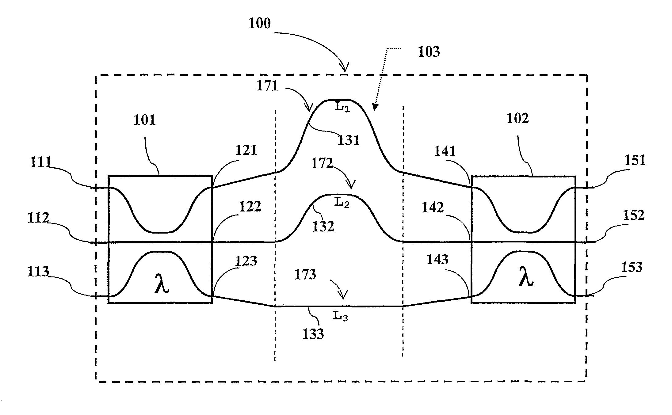
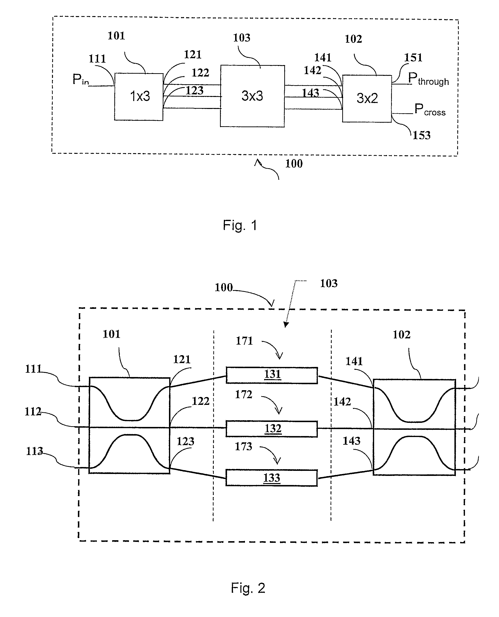
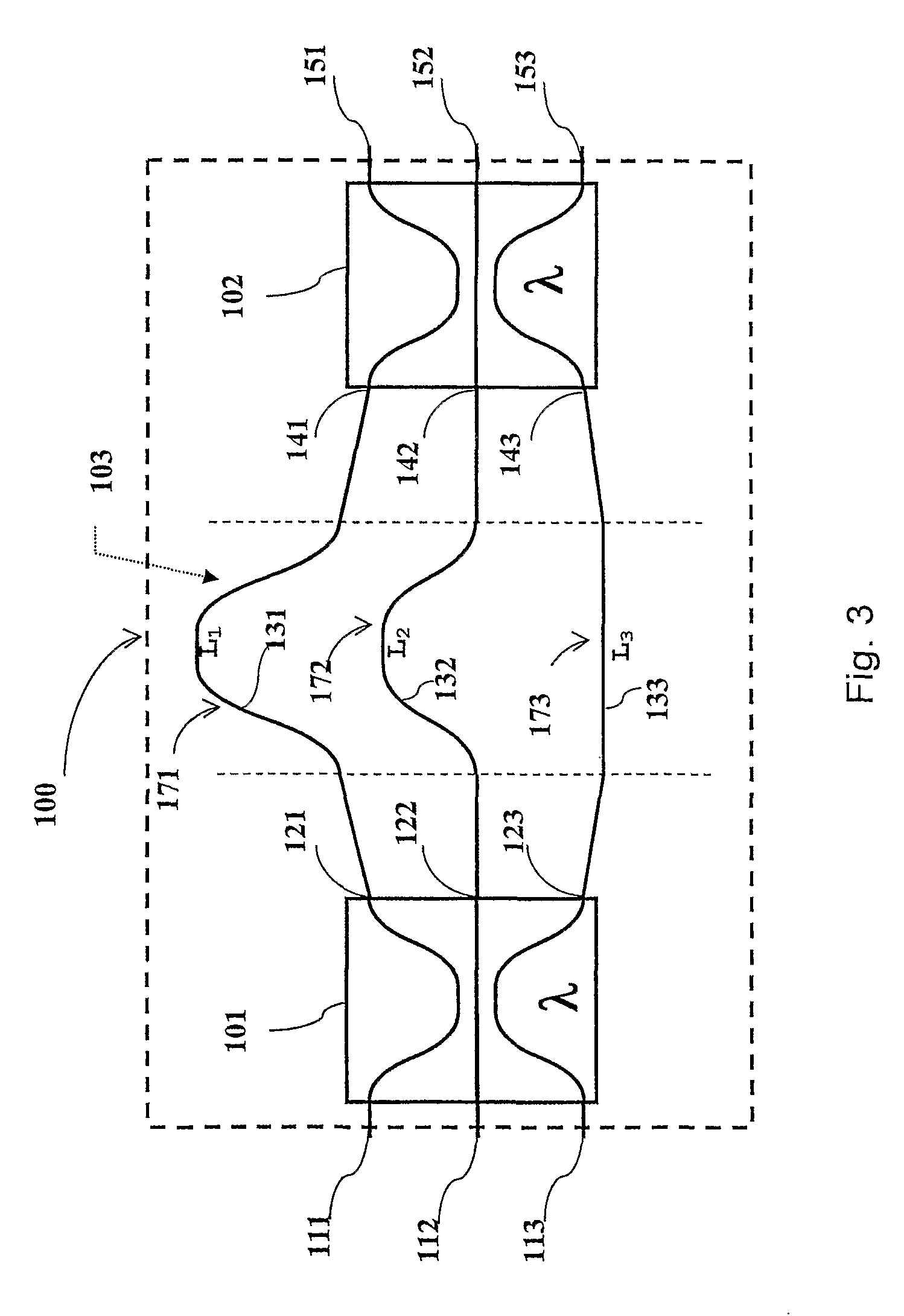
[0106]FIG. 1 shows an optical device 100 according to the invention for splitting / combining a first and a second optical wavelength band comprising a first and a second optical splitting / combining element 101, 102 optically coupled in cascade and a differential phase delay device 103 optically interposed between them.

[0107]Each of the optical splitting / combining element 101, 102 is of the (25-50-25% λx) / (0-0-100% λy) type and comprises a first, a second and a third optical path, wherein the first optical path is coupled to the second optical path and the second optical path is coupled to the third optical path at a coupling region of the splitting / combining element 101, λx is a wavelength within the first optical band and λy is a wavelength within the second optical band.

[0108]For the purpose of the present invention, ‘optical path’ corresponds, in the more general meaning thereof, to at least one optical mode that may propagate within the optical device.

[0109]Typically, the first, ...


PUM


Abstract

A three-arm-Mach-Zehnder interferometer for splitting / combining a first and a second wavelength band, wherein the optical device includes: a first and second optical splitting / combining element; a differential optical delay device comprising a first, a second and a third optical path; each of the first and second optical splitting / combining elements, is of the (25-50-25%)λx(0-0-100%)λy type, wherein λx is a wavelength with the first optical band and λy is a wavelength with the second optical band, and the first, second and third optical paths of the differential optical delay device are configured to introduce, at a wavelength λz within the first optical band, a phase delay Δφ of 2πm.

Description

CROSS REFERENCE TO RELATED APPLICATION[0001]This application is a national phase application based on PCT / EP2005 / 001444, filed Feb. 10, 2005, the content of which is incorporated herein by reference.BACKGROUND OF THE INVENTION[0002]1. Field of the Invention[0003]The present invention relates to an optical device for splitting / combining a first and a second optical wavelength band.[0004]Moreover, the present invention relates to an apparatus for splitting / combining a first and a second optical wavelength band, comprising at least two of said optical devices optically connected in cascade.[0005]The present invention further relates to an optical unit and an optical network comprising at least one of said optical devices.[0006]2. Description of the Related Art[0007]In the present description and claims the expression[0008]“transfer function” with reference to an output port and an input port of an optical device is used to indicate the ratio of the output optical power from the output ...

Claims


Application Information

Patent Timeline
IPC IPC(8): H04J14/00
CPCG02B6/29352G02B6/12011G02B6/12021
Inventor COSTA, RAFFAELLACUSMAI, GIUSEPPEMELLONI, ANDREA
Owner GOOGLE LLC
Learn More