Turbine blade with dual serpentine cooling

a turbine blade and serpentine technology, applied in the direction of liquid fuel engines, vessel construction, marine propulsion, etc., can solve the problems of reducing the cooling performance of the serpentine flow circuit, limiting the material inlet temperature to the properties of the turbine blade, and high leakage flow, so as to achieve low gas temperature conditions

Inactive Publication Date: 2011-09-27
FLORIDA TURBINE TECH
View PDF7 Cites 17 Cited by
  • Summary
  • Abstract
  • Description
  • Claims
  • Application Information

AI Technical Summary

Benefits of technology

[0011]It is an object of the present invention to provide for a turbine b...

Problems solved by technology

However, the turbine inlet temperature is limited to the material properties of the first stage vanes and blades and the amount of cooling that can be achieved for these airfoils.
In order to satisfy the back flow margin criteria, a high cooling supply pressure is needed for this particular design, and thus inducing a high leakage flow.
Cooling air bled off from the 5-p...

Method used


Image

  • Turbine blade with dual serpentine cooling
  • Turbine blade with dual serpentine cooling
  • Turbine blade with dual serpentine cooling

Examples


Embodiment Construction

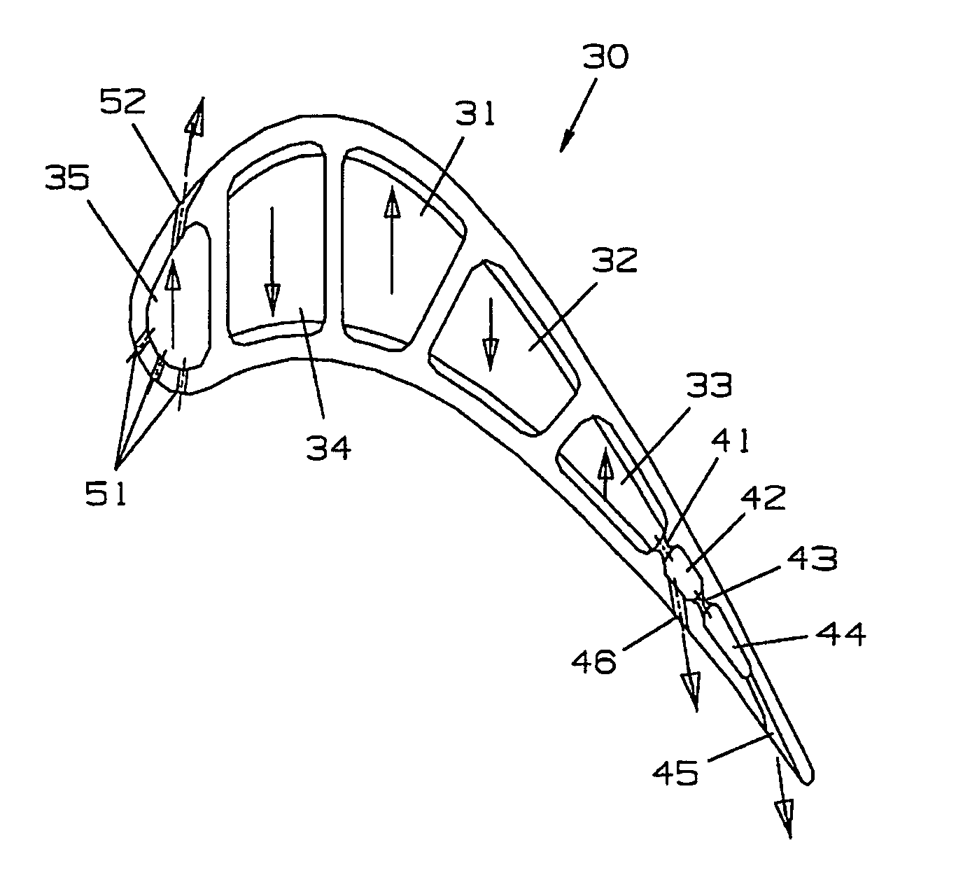
[0020]The 6-pass serpentine flow cooling circuit of the present invention is intended for use in a turbine rotor blade of an IGT, but could also be used in an aero engine rotor blade. FIG. 5 shows a turbine rotor blade 30 with the 6-pass serpentine flow cooling circuit of the present invention which includes a first leg or channel 31 that supplies the pressurized cooling air from an external source to the blade cooling circuit, a second leg 32 located aft of the first leg 31, a third leg 33 located adjacent to a trailing edge region of the blade airfoil, a fourth leg 34 located forward of the first leg 31, a fifth leg 35 located adjacent to the leading edge of the airfoil, and a sixth leg 36 (see FIG. 6) located under the tip cap and extending along a chordwise direction of the blade. The legs 31-25 form cooling air channels from the platform region to the tip region that extend from the pressure side wall to the suction side wall and include chevron trip strips to promote heat tran...


PUM


Abstract

A turbine rotor blade with a low cooling flow serpentine circuit to provides cooling for the airfoil. The circuit includes a three pass aft flowing serpentine circuit that begins at the airfoil mid-chord region and connects to a series of multiple impingement cooling holes formed within the trailing edge region. A double pass forward flowing serpentine circuit then connects with the triple pass aft flowing serpentine circuit to provide cooling for the leading edge region and is connected to a showerhead arrangement for discharging film cooling air. A blade tip cooling channel connects with the last leg of the double pass forward flowing serpentine to form a 6-pass serpentine flow cooling circuit for the entire blade. Since only the leading edge serpentine channel discharges film cooling air, the serpentine circuit can make use of low cooling flow to provide cooling for the entire blade.

Description

GOVERNMENT LICENSE RIGHTS[0001]None.CROSS-REFERENCE TO RELATED APPLICATIONS[0002]None.BACKGROUND OF THE INVENTION[0003]1. Field of the Invention[0004]The present invention relates generally to a gas turbine engine, and more specifically to an air cooled blade in a gas turbine engine.[0005]2. Description of the Related Art including information disclosed under 37 CFR 1.97 and 1.98[0006]A gas turbine engine includes a turbine with multiple rows or stages of rotor blades that react with a high temperature gas flow to drive the engine or, in the case of an industrial gas turbine (IGT), drive an electric generator and produce electric power. It is well known that the efficiency of the engine can be increased by passing a higher temperature gas flow into the turbine. However, the turbine inlet temperature is limited to the material properties of the first stage vanes and blades and the amount of cooling that can be achieved for these airfoils.[0007]In latter stages of the turbine, the gas...

Claims


Application Information

Patent Timeline
IPC IPC(8): F01D5/18
CPCF01D5/187F05D2250/185F05D2260/221
Inventor LIANG, GEORGE
Owner FLORIDA TURBINE TECH
Why Eureka
Try Eureka