Electro-optical devices using dynamic reconfiguration of effective electrode structures

a technology of effective electrode structure and electro-optical device, which is applied in the direction of static indicating device, door/window protective device, instruments, etc., can solve the problems of difficult to produce the required thickness of high resistivity material with high optical transparency, low yield of manufacturing process, and inability to switch between diverging and converging lenses, so as to reduce image aberration, improve lens performance, avoid disclination of lc layer

Active Publication Date: 2011-10-04
POINT FINANCIAL
View PDF35 Cites 15 Cited by
  • Summary
  • Abstract
  • Description
  • Claims
  • Application Information

AI Technical Summary

Benefits of technology

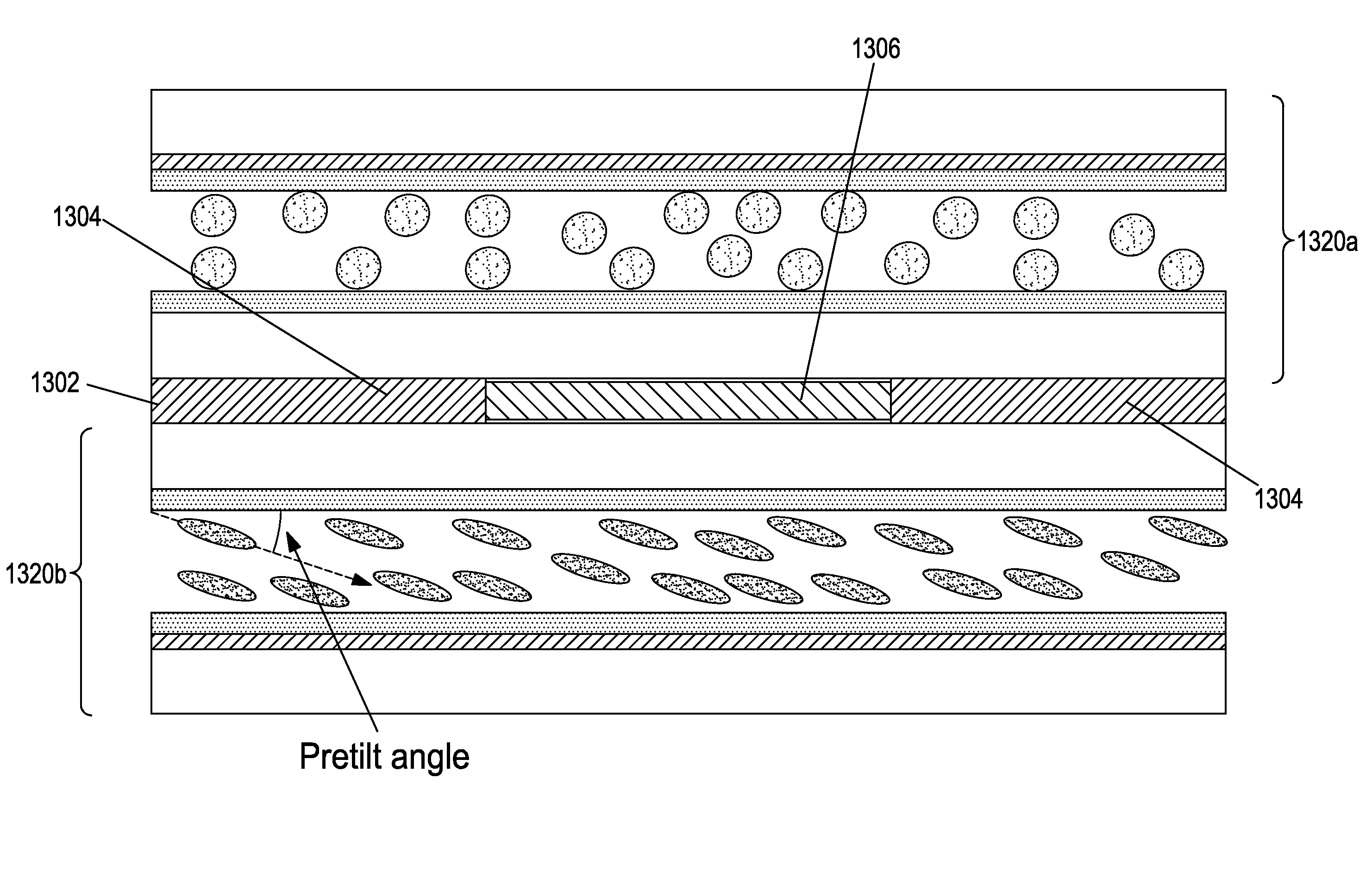
[0007]In accordance with the present invention, a variable optical device is provided for controlling the propagation of light passing therethrough, where the device makes use of a frequency dependent material and an electrical signal generator that generates a drive signal at a plurality of different frequencies. The device includes a liquid crystal (LC) layer through which the light passes, the LC layer controlling the light propagation. An electrode system is also provided that is connected to the electrical signal generator and arranged to generate an electric field that acts on the LC layer to alter its optical properties. The electrical signal generator generates a drive signal at a plurality of different frequencies and supplies the drive signal to the electrode system so as to generate the electric field. The frequency dependent material is located in the device so that it interacts with the electric field. This material has a charge mobility that is dependent on a frequency of the drive signal such that a spatial profile of the electric field varies as a function of the drive signal frequency to alter the properties of the LC layer. “Charge mobility” is used to describe the property of the frequency dependent material instead of “conductivity” because the latter can be understood to describe the mean free path of electrons. At low frequencies, some frequency dependent materials that exhibit high charge mobility may actually have lower conductivity (i.e. a shorter mean free path of electrons) than at higher frequencies, however, since the time for the charge to flow within the frequency dependent material is longer at low frequencies, this can result in less charge flow. Similarly, at higher frequencies, the mean free path of electrons in some materials may be longer, however, given the shorter time that the electric potential is available in each positive or negative cycle, the resulting charge flow may be greatly reduced. Thus “charge mobility” is used to refer to the overall ability of charge to flow within the frequency dependent material within the constraints of the alternating electric signal applied.
[0015]A basic concept of the invention is using a frequency dependent material in conjunction with different drive signal frequencies in order to change an effective electrode structure within the optical device. The electrode structure determines the profile of the electric field which, in turn, determines the optical properties of the LC layer. The frequency dependent material may be selected to exhibit different charge mobility at different frequencies such that, at different frequencies, it may appear as a conductive or as a non-conductive material. For frequencies at which it appears as a conductor, the frequency dependent material may create an effective electrode structure that is positioned differently than one of the fixed electrodes. However, for frequencies at which charge mobility in the frequency dependent material is relatively low, it does not appear as a conductor, and the effective electrode structure is determined by the actual position of the fixed electrodes. Thus, with proper positioning of a frequency dependent material, and the selection of different drive frequencies, the effective conductor configuration may be altered and the optical properties of the LC layer dynamically changed.
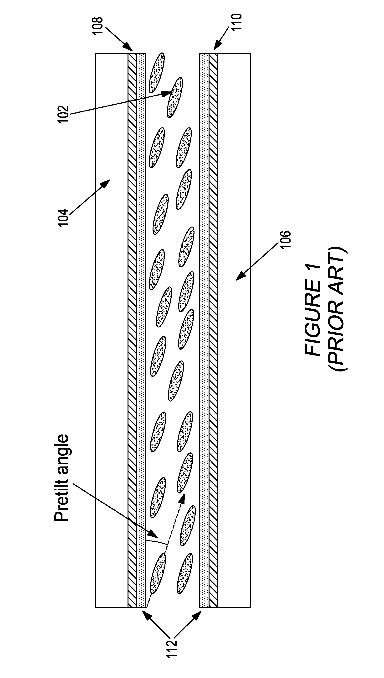
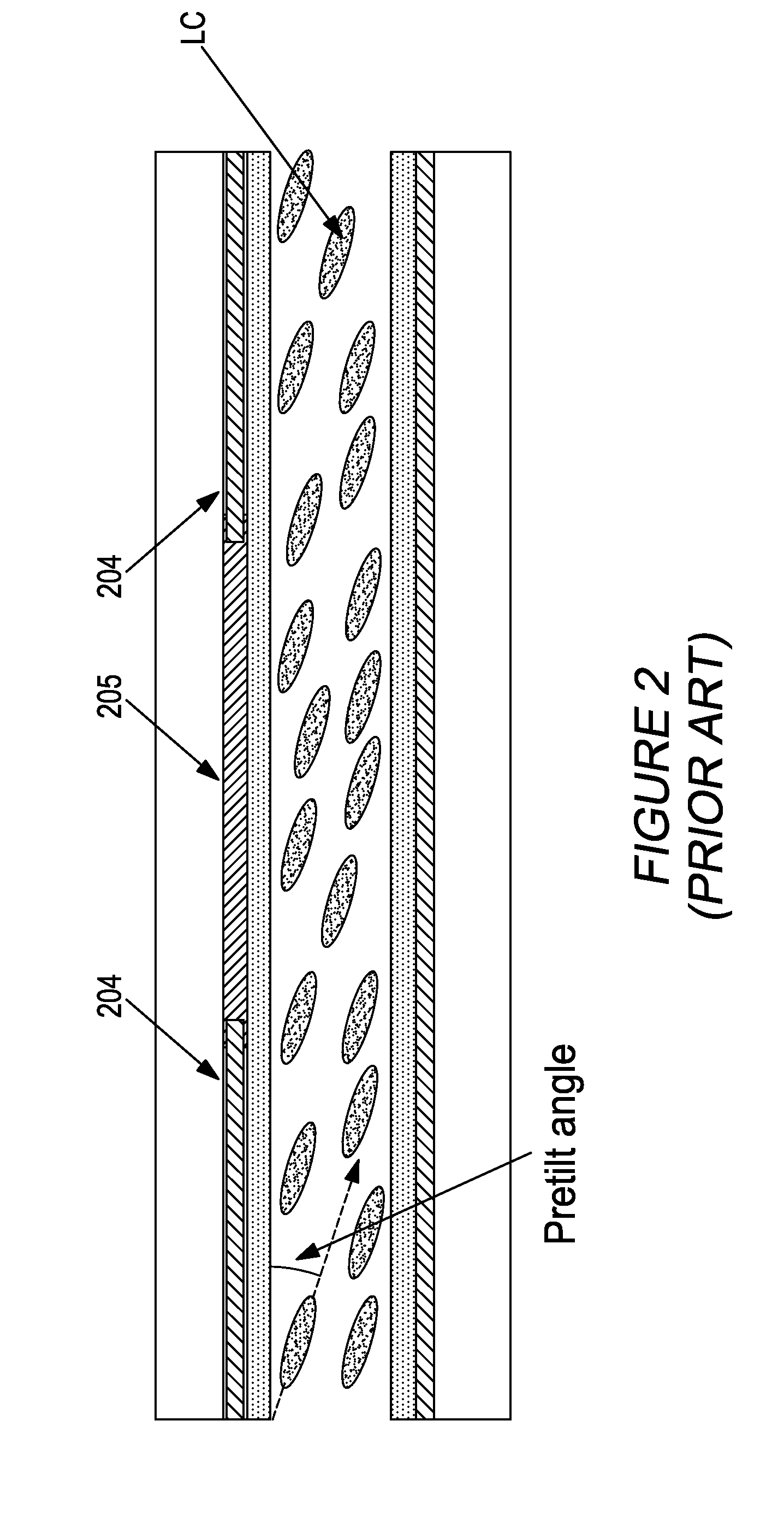
[0029]For example, an LC layer may be used that has a low angle pre-tilt alignment layer, and a first frequency may be applied for which the effective electrode structure is uniform. At this frequency, the voltage may then be increased to a level at which the LC molecules all have an initial reorientation at a uniform tilt. The frequency of the voltage may then be changed to modify the effective voltage structure and introduce non-uniformities into the electric field so as to change the optical characteristic of the liquid crystal, such as to form a lens structure. By applying an initial uniform electric field strength to the liquid crystal before introducing field non-uniformities, disclinations in the LC layer are avoided. The drive signal may also be applied so as to prevent the liquid crystals from remaining close to a ground state, and to thereby reduce image aberrations. In another example, frequency control may be used to alter the optical power of LC lens, but the voltage of the drive signal switched from one level to another at different optical powers so as to improve the performance of the lens. Many other similar control paradigms are likewise possible.

Problems solved by technology

Unfortunately, it is difficult to produce the required thickness of high resistivity material with high optical transparency, as well as an LC cell with good uniformity, and the manufacturing process typically has a low yield.
It is not possible to switch between a diverging and converging lens.
Unfortunately, the complex patterning of the top electrode, the necessity of using two distinct voltages and a separate WCL are difficult to manufacture and inhibit the practical use of this approach.
For example, the use of this approach to build a polarization independent lens would require the use of six to seven thick glasses, which is a difficult task.

Method used


Image

  • Electro-optical devices using dynamic reconfiguration of effective electrode structures
  • Electro-optical devices using dynamic reconfiguration of effective electrode structures
  • Electro-optical devices using dynamic reconfiguration of effective electrode structures

Examples


Embodiment Construction

en using a drive signal having a relatively high frequency.

[0065]FIG. 27C is a graphical view showing equipotential planes for the configuration of FIG. 27A when using a drive signal having a relatively low frequency.

[0066]FIG. 28A is a schematic view of a structure similar to that of FIG. 27A but with a shaped top electrode having an inverted shape to provide an opposite tunability.

[0067]FIG. 28B is a schematic view of a structure having a top electrode with a shape having all flat surfaces, and a flat aperture polymer structure.

[0068]FIG. 28C is a schematic view of a structure similar to that of FIG. 28B, but for which the positions of the flat surfaces are reversed so as to provide an opposite tunability.

[0069]FIG. 29A is a schematic view of a structure having a top electrode with a curved layer of frequency dependent material encased in a top layer of polymer material.

[0070]FIG. 29B is a graphical view showing the maximum angle of reorientation of LC molecules for the lens confi...


PUM

PropertyMeasurementUnit
dielectric constantaaaaaaaaaa
voltagesaaaaaaaaaa

Abstract

Variable liquid crystal devices for controlling the propagation of light through a liquid crystal layer use a frequency dependent material to dynamically reconfigure effective electrode structures in the device. The frequency of a drive signal that generates an electric field in the device may be varied, and the frequency dependent material has different charge mobilities for the different frequencies. At a low charge mobility, the frequency dependent material has little effect on the existing electrode structures. However, at a high charge mobility, the frequency dependent material appears as an extension of the fixed electrodes, and may be used to change the effective electrode structure and, thereby, the spatial profile of the electric field. This, in turn, changes the optical properties of the liquid crystal, thus allowing the optical device to be frequency controllable.

Description

CROSS-REFERENCE TO RELATED APPLICATIONS[0001]This application is a divisional of U.S. application Ser. No. 13 / 000,601, a 35 U.S.C 371 National Stage on International Application Ser. No. PCT / IB2009 / 052658 filed Jun. 21, 2009 claiming priority of U.S. Provisional Application Ser. No. 61 / 074,618, filed Jun. 21, 2008; U.S. Provisional Application Ser. No. 61 / 074,621, filed Jun. 21, 2008; U.S. Provisional Application Ser. No. 61 / 074,653, filed Jun. 22, 2008; U.S. Provisional Application Ser. No. 61 / 074,654, filed Jun. 22, 2008; U.S. Provisional Application Ser. No. 61 / 080,404, filed Jul. 14, 2008; and U.S. Provisional Application Ser. No. 61 / 142,186, filed Dec. 31, 2008, which are incorporated herein by reference in their entirety.FIELD OF THE INVENTION[0002]This invention relates to the field of electrically tunable optical devices, particularly those using liquid crystal.BACKGROUND OF THE INVENTION[0003]Tunable liquid crystal (LC) optical devices, such as lenses, beam steering devices...

Claims


Application Information

Patent Timeline
Patent Type & Authority Patents(United States)
IPC IPC(8): G02F1/1335
CPCC08J3/28G02F1/29G02F1/1337G02F1/134309G02F1/13306G02F2001/294G02F2001/133749G02F1/294G02F1/133749G02F2203/24
Inventor GALSTIAN, TIGRANPRESNIAKOV, VLADIMIRASATRYAN, KARENTORK, AMIRZOHRABIAN, ARMENBAGRAMIAN, ARAM
Owner POINT FINANCIAL
Why Eureka
Try Eureka