Implant, arrangement comprising an implant, and method for inserting said implant in bone tissue

a technology of implant and bone tissue, which is applied in the field of screw implants, can solve the problems of bone resorption, secondary problems, and failure of the prosthesis, and achieve the effects of reducing the problem of thread damage, easy installation, and good functioning

Inactive Publication Date: 2011-10-04
ASTRA TECH SE
View PDF48 Cites 35 Cited by
  • Summary
  • Abstract
  • Description
  • Claims
  • Application Information

AI Technical Summary

Benefits of technology

[0014]The object of the invention is to provide an implant that, in relation to prior art implants, is easier to install in a correct manner Especially it should diminish the problem of threads being damaged at insertion of the implant. Further, the implant should still be a well functioning implant in other important aspects, such as providing stable primary fixation, initial stability and proper loading of the bone tissue while not being prone to marginal bone resorption.
[0015]The above mentioned object is achieved by a screw implant for insertion into a bore hole arranged in bone tissue, said implant having a cancellous portion, and a cortical portion having an axial length such that, when installed in the bore hole, the engagement of said cortical portion with the bone tissue will generally be confined to the cortical bone tissue layer. Said cortical portion presents an outer surface which is threaded for accomplishing said engagement, and has an outer design such that, when being screwed into said bore hole under action of a screwing torque, said cortical portion acts so as to increase the compression of the cortical bone tissue only, in essentially radial directions of the implant, resulting in a distinct increase of the screwing torque needed for screwing the implant, which increase is usable as an indication that the implant is in place or nearly in place in the bore hole.

Problems solved by technology

A problem occurring when using many prior art screw type implants is referred to as the bone resorption problem.
This is highly undesired, since a diminished amount of bone surrounding the implant will lead to diminished stability and sometimes result in failure of the prosthesis.
Once bone resorption is a fact, secondary problems may also appear.
Such secondary problems, particularly related to dental implants, are for example deposition of plaque, resulting in inflammation in the gingival tissue surrounding the implant, or down-growth of gingival tissue along the exposed end of the implant.
Also, the aesthetic appeal of the implant is undermined by bone tissue resorption, which is an important drawback in particular when the implant is intended for dental applications since dental prosthesis form part of the field of cosmetic surgery.
A disadvantage with the above-mentioned implant might be revealed when installing it, as is common, into a bore hole.
Unfortunately, there is a risk that the surgeon, when having screwed the implant into a position where it has reached the bottom of the bore hole, happens to continue screwing the implant.
Instead, the extra screwing merely rotates the implant in the bore hole, while it remains at the same depth, which rotation causes destruction of the previously cut internal threads in the bore hole.
Without the internal threads, the stability of the implant is impaired.
Less stability leads to longer healing time for the implant, and an increased risk for secondary problems.
Such a secondary problem, being particularly problematic in dental applications is the formation of unwanted soft connective tissue around the implant.
Thus, this implant, although it is provided with some kind of head portion, seems to be prone to the same risk of fracturing the threads in the bore hole as the implant in WO 00 / 03657 (Astra Aktiebolag, Hansson) mentioned above.
However, also in this prior art, the surgeon could easily continue to apply a growing torque even after the implant has reached the end of the hole, thus turning it so as to destroy the previously cut threads of the bore hole.
Accordingly, this conical implant may be prone to the same problem as described above in relation to the implant of WO 00 / 03657 (Astra Aktiebolag, Hansson)
Another disadvantage is that the conical shape of the implant causes a large amount of bone to spread and consequently be subjected to extra loading.
However, the extra loading might over-load the bone tissue, resulting instead in bone resorption and following poor stability of the implant.

Method used


Image

  • Implant, arrangement comprising an implant, and method for inserting said implant in bone tissue
  • Implant, arrangement comprising an implant, and method for inserting said implant in bone tissue
  • Implant, arrangement comprising an implant, and method for inserting said implant in bone tissue

Examples


first embodiment

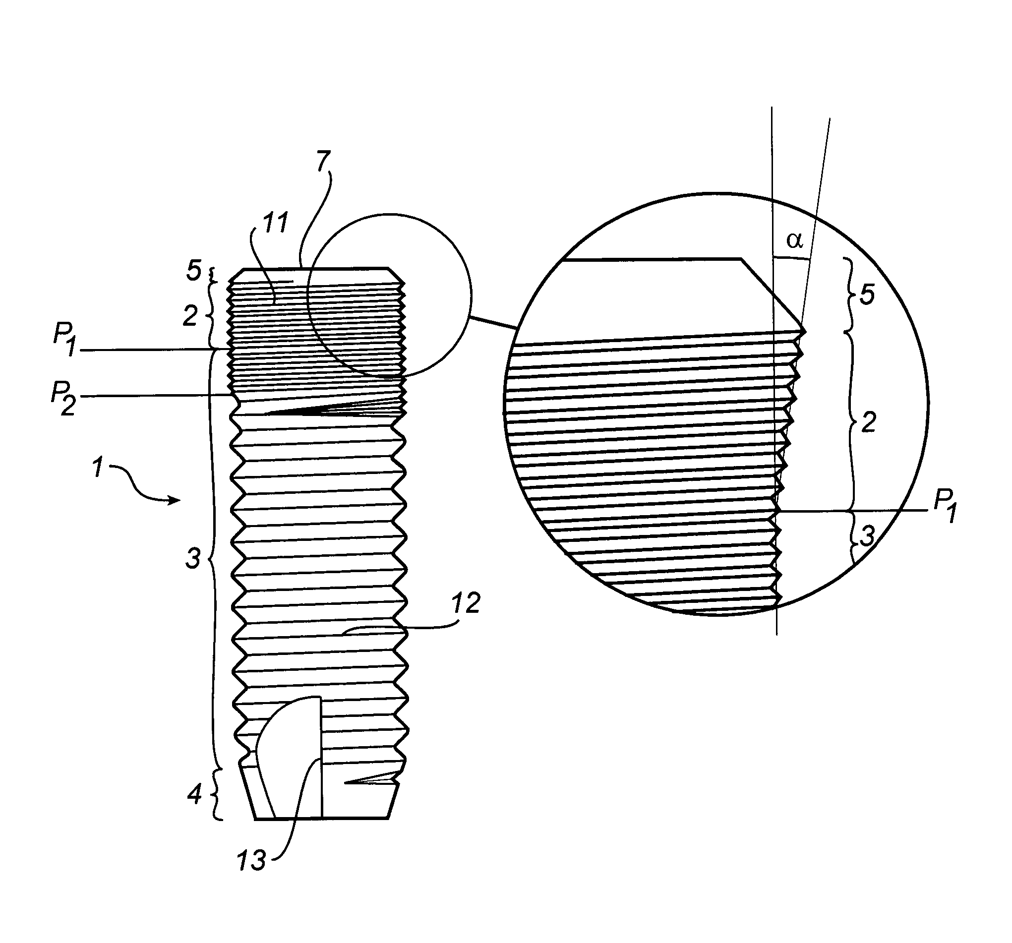
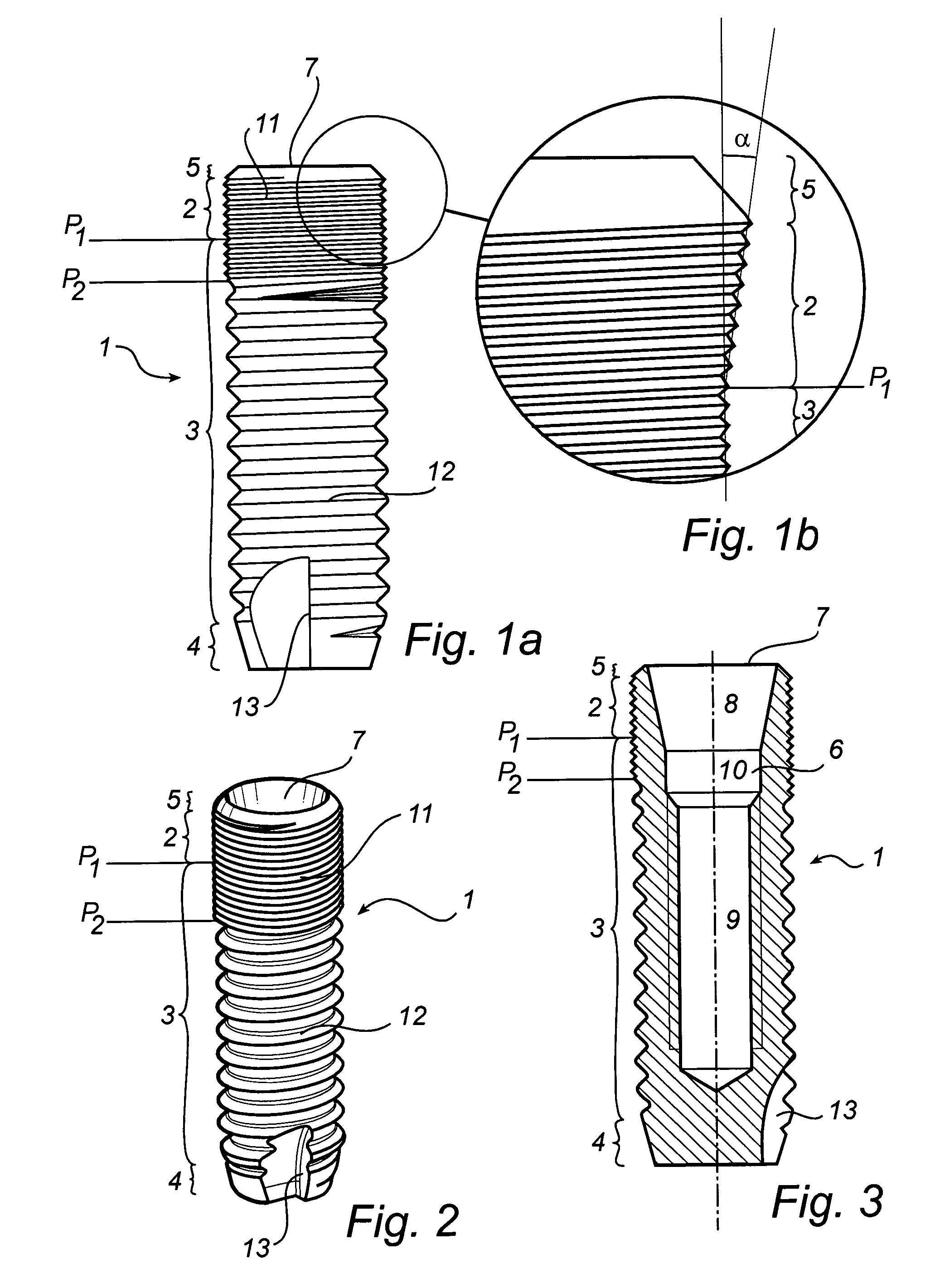
[0077]the invention will now be described in relation to FIGS. 1 to 3. This embodiment shows the inventive concept applied on the previously mentioned prior-art implant as is described in WO 00 / 03657 (Astra Aktiebolag, Hansson), where it is believed to have a particularly advantageous effect.

[0078]The implant 1 having a generally cylindrical shape is a dental implant for insertion into a bore hole drilled in the bone tissue of a maxilla or mandible, for anchorage of a prosthesis. The implant 1 is made from commercially pure titanium, a titanium alloy, another biocompatible metal or metal alloy or a ceramic to promote osseointegration of the implant with the bone tissue of the boundary walls of the bore hole.

[0079]The length of the implant 1 is preferably between 8-19 mm and the maximum width around 3-4 mm. The implant 1 depicted in FIGS. 1a to 3 has a length of 12 mm, and a width of 4 mm.

[0080]The implant has a cancellous portion 3 presenting a cylindrical outer surface, and a corti...

second embodiment

[0095]In FIGS. 5a and 5b the invention is shown. This implant is a variant of the implant described in connection to FIGS. 1 to 3. The implant depicted in FIGS. 5a and 5b differs from the implant of FIG. 1 in that only the cortical portion 2 is provided with microthreads, whereas all lower parts of the implant are provided with macrothreads. In other words, the border plane P2 between the first and second threadings 11 and 12 coincides with the border plane P1 between the cortical portion 2 and the cancellous portion 3.

[0096]The first threading 11 merges with the second threading 12 in the same manner as described in relation to the first embodiment. Thus, also in this embodiment the threaded outer surface of the cortical portion 2 engages in the same internal threads as the cancellous portion 3, facilitating the insertion of the cortical portion 2 in the bore hole.

third embodiment

[0097]In FIGS. 6a and 6b the invention is shown. This implant is yet another variant of the implant described in connection to FIGS. 1 to 3, differing from the implant in FIG. 1 in that there is only one threading 11 provided on the implant.

[0098]The threading 11 extends with no interruption over the tip portion 4, the cancellous portion 3, and the cortical portion 2. In this case, the threading 11 has a triple micro-thread. The micro-thread is believed to contribute to a favourable load distribution around the implant, in particular for inhibiting bone resorption.


PUM


Abstract

The present invention relates to a screw implant (1) for insertion into a bore hole (50) arranged in bone tissue, said implant having a cancellous portion (3), and a cortical portion (2) having an axial length such that, when installed in the bore hole (50), the engagement of said cortical portion (2) with the bone tissue will generally be confined to the cortical bone tissue layer (52). Said cortical portion (2) presents an outer surface which is threaded for accomplishing said engagement, and has an outer design such that, when being screwed into said bore hole under action of a screwing torque, said cortical portion (2) acts so as to increase the compression of the cortical bone tissue only, in essentially radial directions of the implant, resulting in a distinct increase of the screwing torque needed for screwing the implant (1). Said increase is usable as an indication that the implant (1) is in place or nearly in place in the bore hole.The invention also relates to an arrangement comprising an implant and a bore hole, and a method for insertion of an implant into a bore hole.

Description

[0001]This application is the national phase under 35 U.S.C. §371 of PCT International Application No. PCT / SEO2 / 01458 which has an International filing date of Aug. 14, 2002, which designated the United States of America.FIELD OF THE INVENTION[0002]The invention relates to a screw implant for insertion into a bore hole arranged in bone tissue, said implant having a cancellous bone engagement portion, referred to as cancellous portion, and a cortical portion having an axial length such that, when installed in the bore hole, the engagement of said cortical portion with the bone tissue will generally be confined to the cortical bone tissue layer. Said cortical portion presents an outer surface which is threaded for accomplishing said engagement. It further relates to an arrangement for facilitating insertion of a screw implant in bone tissue including a screw implant and a bore hole. The invention also relates to a method of inserting an implant into a bore hole.BACKGROUND OF THE INVEN...

Claims


Application Information

Patent Timeline
Patent Type & Authority Patents(United States)
IPC IPC(8): A61C8/00
CPCA61C8/0025A61C8/0022A61C8/00
Inventor HOLMEN, ANDERSRASMUSSON, LARSWENDEL, MATS
Owner ASTRA TECH SE
Why Eureka
Try Eureka