Methods for the synthesis of arrays of DNA probes

a synthesis method and array technology, applied in the field of biology, can solve the problems of long processing time, high cost, laborious and time-consuming conventional dna sequencing using electrophoresis, etc., and achieve the effect of avoiding time-consuming manipulation and avoiding significant costs and time delays

Inactive Publication Date: 2011-10-04
WISCONSIN ALUMNI RES FOUND
View PDF63 Cites 42 Cited by
  • Summary
  • Abstract
  • Description
  • Claims
  • Application Information

AI Technical Summary

Benefits of technology

[0007]In accordance with the present invention, the synthesis of arrays of DNA probe sequences, polypeptides, and the like is carried out rapidly and efficiently using patterning processes. The process may be automated and computer controlled to allow the fabrication of a one or two-dimensional array of probes containing probe sequences customized to a particular investigation. No lithographic masks are required, thus eliminating the significant costs and time delays associated with the production of lithographic masks and avoiding time-consuming manipulation and alignment of multiple masks during the fabrication process of the probe arrays.
[0009]The image is projected onto the substrate utilizing an image former having an appropriate light source that provides light to a micromirror device comprising a two-dimensional array of electronically addressable micromirrors, each of which can be selectively tilted between one of at least two separate positions. In one of the positions of each micromirror, the light from the source incident on the micromirror is deflected off an optical axis and away from the substrate, and in a second of the at least two positions of each micromirror, the light is reflected along the optical axis and toward the substrate. Projection optics receive the light reflected from the micromirrors and precisely image the micromirrors onto the active surface of the substrate. Collimating optics may be used to collimate the light from the source into a beam provided directly to the micromirror array or to a beam splitter, wherein the beam splitter reflects a portion of the beam to the micromirror array and transmits reflected light from the micromirror array through the beam splitter. The light directly reflected from the micromirrors or transmitted through the beam splitter is directed to projection optics lenses which image the micromirror array onto the active surface of the substrate. Because the selectively addressable micromirrors in the micromirror array may either fully reflect or fully deflect the light provided to them, the image of the micromirror array exhibits a very high contrast between the “on” and “off” pixels. The micromirrors may also be capable of being indexed to more than two positions, in which case additional optics may be provided to allow exposure of more than one substrate using a single micromirror array device. In addition, the micromirrors are capable of reflecting light at any wavelength without damage to them, allowing short wavelength light, including light in the range of ultraviolet to near ultraviolet light, to be utilized from the light source.
[0010]The micromirror array is operated under control of a computer which provides appropriate pixel address signals to the micromirror array to cause the appropriate micromirrors to be in their “reflect” or “deflect” positions. The appropriate micromirror array pattern for each activation step in each level of bases to be added to the probes is programmed into the computer controller. The computer controller thus controls the sequencing of the images presented by the micromirror array in coordination with the reagents provided to the substrate.

Problems solved by technology

The conventional sequencing of DNA using electrophoresis is typically laborious and time consuming.
A disadvantage of both of these approaches is that four different lithographic masks are needed for each monomeric base, and the total number of different masks required are thus four times the length of the DNA probe sequences to be synthesized.
The high cost of producing the many precision photolithographic masks that are required, and the multiple processing steps required for repositioning of the masks for every exposure, contribute to relatively high costs and lengthy processing times.

Method used


Image

  • Methods for the synthesis of arrays of DNA probes
  • Methods for the synthesis of arrays of DNA probes
  • Methods for the synthesis of arrays of DNA probes

Examples


Embodiment Construction

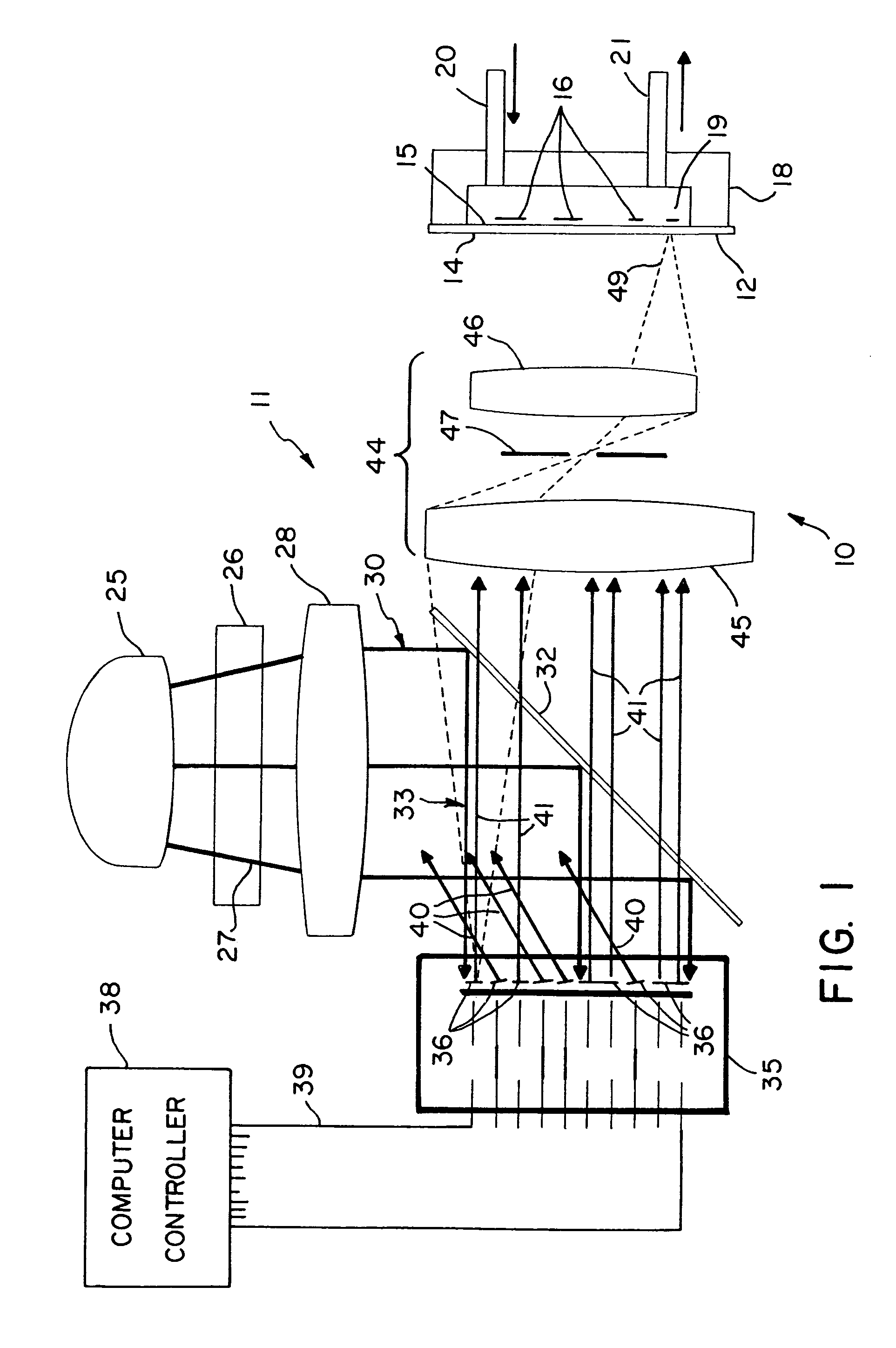
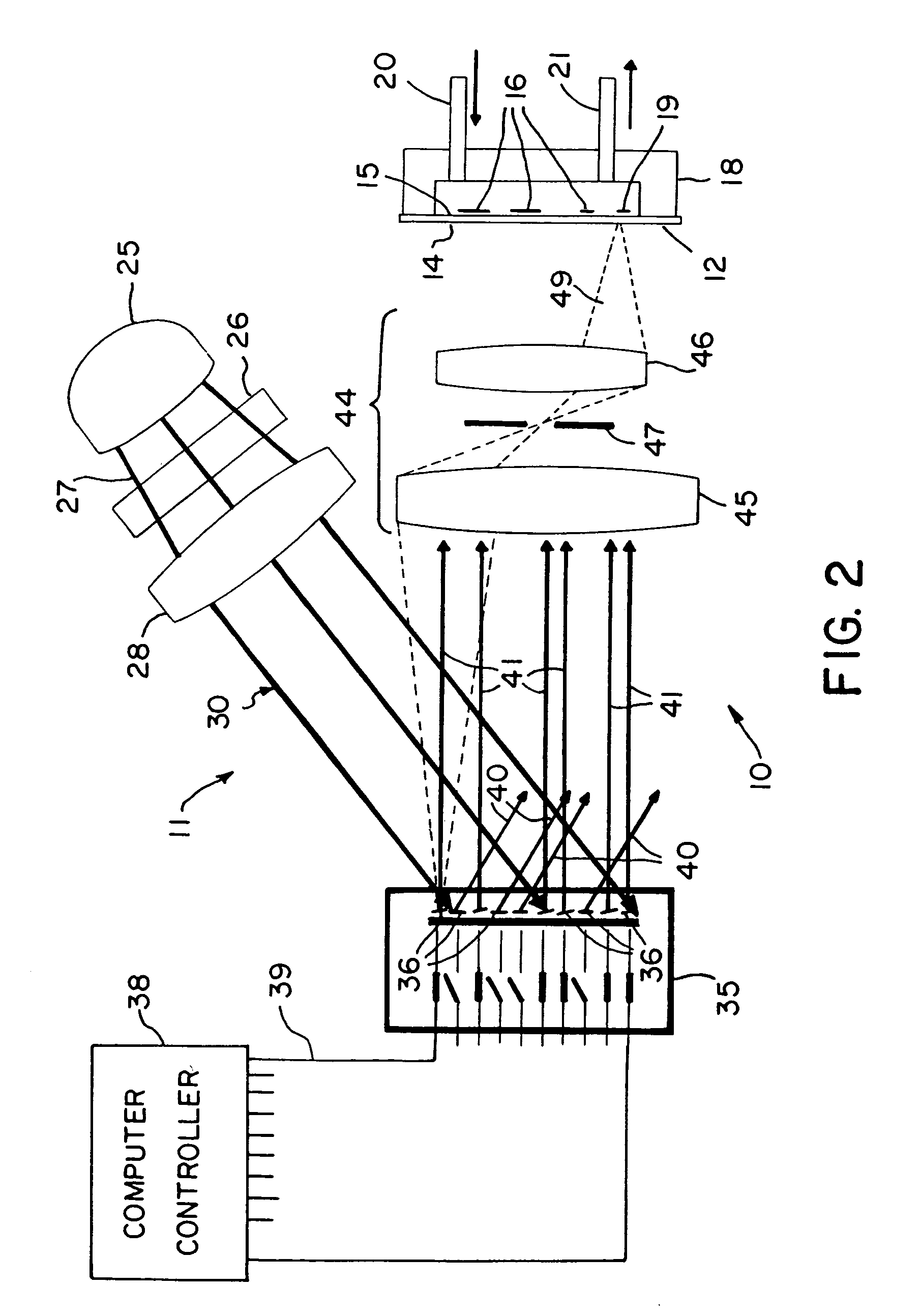
[0028]With reference to the drawings, an exemplary apparatus that may be used for DNA probe array synthesis, polypeptide synthesis, and the like is shown generally at 10 in FIG. 1 and includes a two-dimensional array image former 11 and a substrate 12 onto which the array image is projected by the image former 11. For the configuration shown in FIG. 1, the substrate has an exposed entrance surface 14 and an opposite active surface 15 on which a two-dimensional array of nucleotide sequence probes 16 are to be fabricated. For purposes of illustration, the substrate 12 is shown in the figure with a flow cell enclosure 18 mounted to the substrate 12 enclosing a volume 19 into which reagents can be provided through an input port 20 and an output port 21. However, the substrate 12 may be utilized in the present system with the active surface 15 of the substrate facing the image former 11 and enclosed within a reaction chamber flow cell with a transparent window to allow light to be projec...


PUM

PropertyMeasurementUnit
wavelengthsaaaaaaaaaa
lengthaaaaaaaaaa
wavelengthaaaaaaaaaa

Abstract

The synthesis of arrays of DNA probes sequences, polypeptides, and the like is carried out using a patterning process on an active surface of a substrate. An image is projected onto the active surface of the substrate utilizing reflective projection optics. The projection optics project a light image onto the active surface of the substrate to deprotect linker molecules thereon. A first level of bases may then be applied to the substrate, followed by development steps, and subsequent exposure of the substrate utilizing a different light image, with further repeats until the elements of a two dimensional array on the substrate surface have an appropriate base bound thereto.

Description

CROSS REFERENCE TO RELATED APPLICATIONS[0001]This application is a continuation of prior application Ser. No. 09 / 637,891 filed Aug. 9, 2000, which is a continuation of prior application Ser. No. 09 / 253,460 filed Feb. 22, 1999, which application claimed the benefit of provisional patent application Ser. No. 60 / 075,641, filed Feb. 23, 1998.STATEMENT OF GOVERNMENT RIGHTS[0002]This invention was made with United States government support awarded by the following agencies: DOE Grant Nos.: DE-FG07-96ER13938; P0062242-02; DE-FG02-96ER45569; 63040304; P071760302; NSF Grant Nos.: IBN-9706552; ECS-9317745; INT-960289; ONR DOD-Navy Grant# N00014-97-1-0460; DOD-Army Grant # DAAH04-95-1-0456; USDA AGRICCREE Grant No.: 95-37304-2364. The United States has certain rights in this invention.FIELD OF THE INVENTION[0003]This invention pertains generally to the field of biology and particularly to techniques and apparatus for the analysis and sequencing of DNA and related polymers.BACKGROUND OF THE INV...

Claims


Application Information

Patent Timeline
Patent Type & Authority Patents(United States)
IPC IPC(8): C07H21/00C12M1/36G02B26/08B01J19/00G01N33/53C07B61/00C12M1/34C40B40/06C40B60/14G01N21/05G01N21/17G01N37/00G03F7/20
CPCB01J19/0046B82Y30/00C07H21/00G02B26/0841G03F7/2002B01J2219/00439B01J2219/00527B01J2219/00529B01J2219/00585B01J2219/0059B01J2219/00596B01J2219/00605B01J2219/00608B01J2219/00612B01J2219/00626B01J2219/00637B01J2219/00641B01J2219/00659B01J2219/00689B01J2219/00711B01J2219/00722C07B2200/11C40B40/00C40B40/06C40B60/14
Inventor CERRINA, FRANCESCOSUSSMAN, MICHAEL R.BLATTNER, FREDERICK R.SINGH-GASSON, SANGEETGREEN, ROLAND
Owner WISCONSIN ALUMNI RES FOUND
Why Eureka
Try Eureka