
Discharge lamp lighting device

a discharge lamp and lighting device technology, applied in the direction of instruments, light sources, electrical appliances, etc., can solve the problems of increasing the number of parts, increasing the cost, and complicated, and achieve the effects of increasing the filament current, preventing the reduction of the filament temperature, and stable discharg

Inactive Publication Date: 2011-10-04
TABUCHI ELECTRIC CO LTD
View PDF20 Cites 0 Cited by
  • Summary
  • Abstract
  • Description
  • Claims
  • Application Information

AI Technical Summary

Benefits of technology

[0022]The present invention has the one-converter power supply configuration in which the L-C series resonant circuit is connected to the half-bridge or full-bridge circuit, differently from the conventional configuration including a plurality of converter power supplies, and has an effect capable of preventing the reduction in the filament temperature to maintain the stable discharge by increasing the filament current along with the nonstep dimming and the decrease in tube current upon the dimming.
[0023]Regarding the dimming, the DC control and the PWM control are combined, and thereby the present invention has an effect capable of obtaining the wide dimming range.
[0024]The present invention can arbitrarily set the preheat current, and therefore has an effect capable of achieving the increase in lifetime of the discharge lamp and the stable lighting operation.
[0025]By starting from a high oscillation frequency upon activation of the power supply, the present invention can suppress the overshoot of the tube voltage. Also, by adding the frequency smoothing circuit for gradually changing the frequency during the transition period from the preheating period to the lighting operation of the discharge lamp, the present invention has an effect of preventing the lighting trouble and simultaneously reducing the overshoot voltage of the tube voltage.
[0026]By detecting the leak current, tube voltage rise, and tube current rise due to the filament disconnection in the hot cathode type discharge tube to stop oscillation of a separately-excited PWM control IC, the present invention has an effect of enhancing safety.
[0027]By switching between the resonant capacitors to respectively optimize the series L-C resonant circuit frequency-gain curve for the preheating and the lighting, the present invention can respectively obtain the adequate gains for the preheating and the lighting, and the large preheat current and the tube current. Also, the present invention can set the peak frequency of the series L-C resonant circuit and the frequency upon the lighting close to each other, and therefore has an effect capable of surely performing the lighting operation of the hot cathode type discharge lamp just before the peak frequency of the series L-C resonant circuit frequency-gain curve is reached by changing the oscillation frequency of the oscillation circuit to perform the lighting operation after the switching between the resonant capacitors.

Problems solved by technology

However, the above conventional example separately requires a power supply for controlling a tube current of a discharge lamp and that for controlling a filament current, and therefore has a problem that a circuit becomes complicated, and the number of parts is increased, resulting in an increase in cost.

Method used


Image

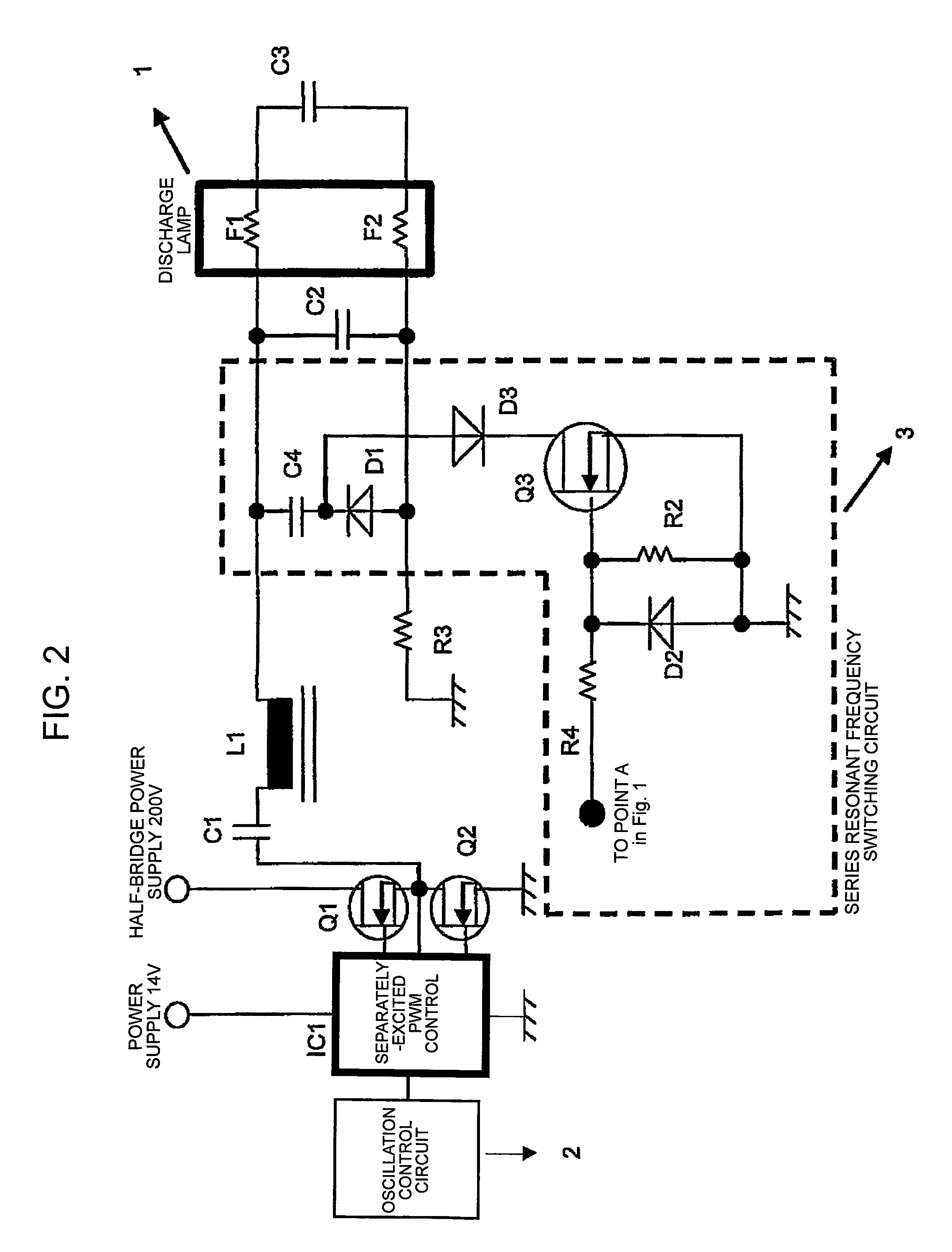
  • Discharge lamp lighting device
  • Discharge lamp lighting device
  • Discharge lamp lighting device

Examples


Embodiment Construction

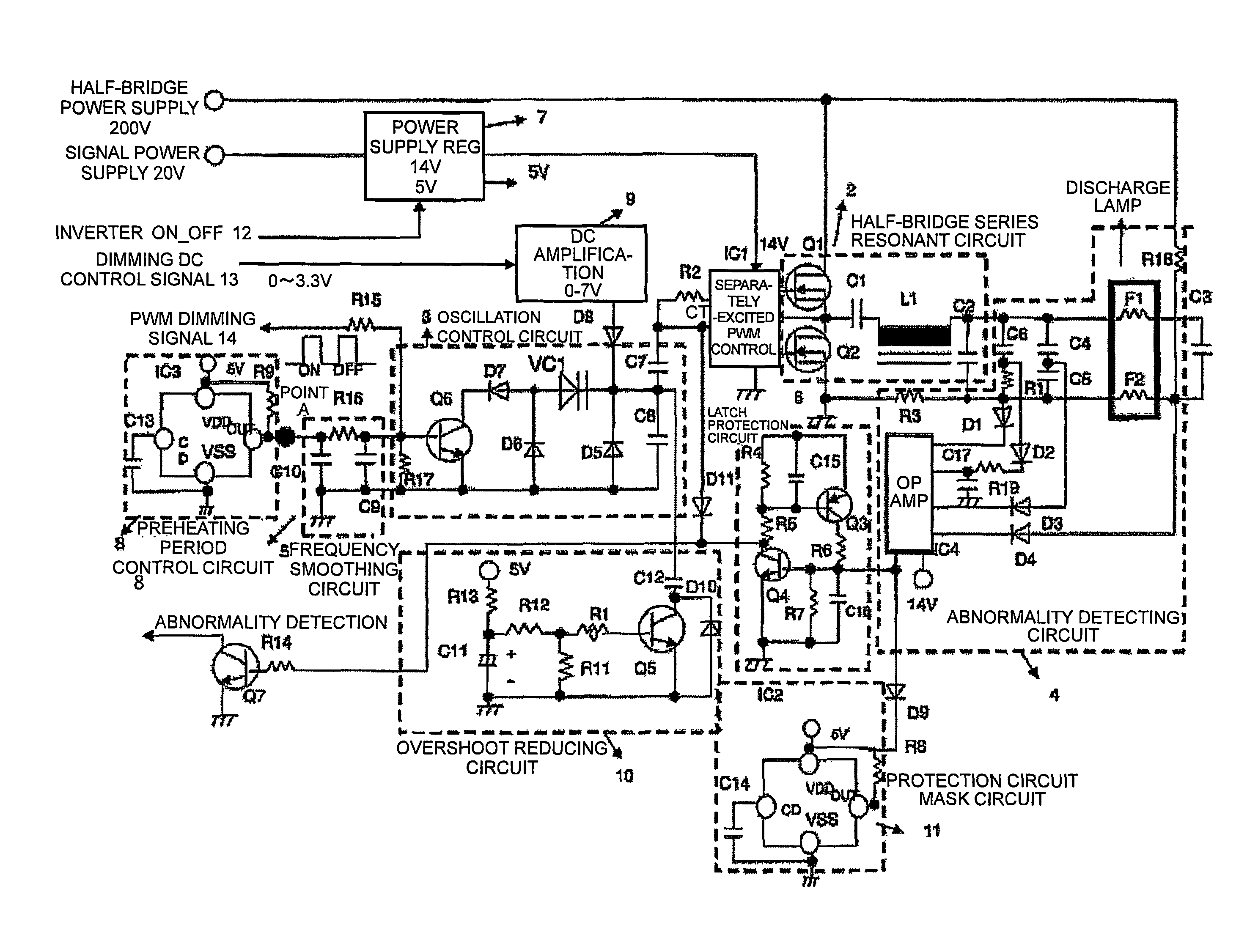
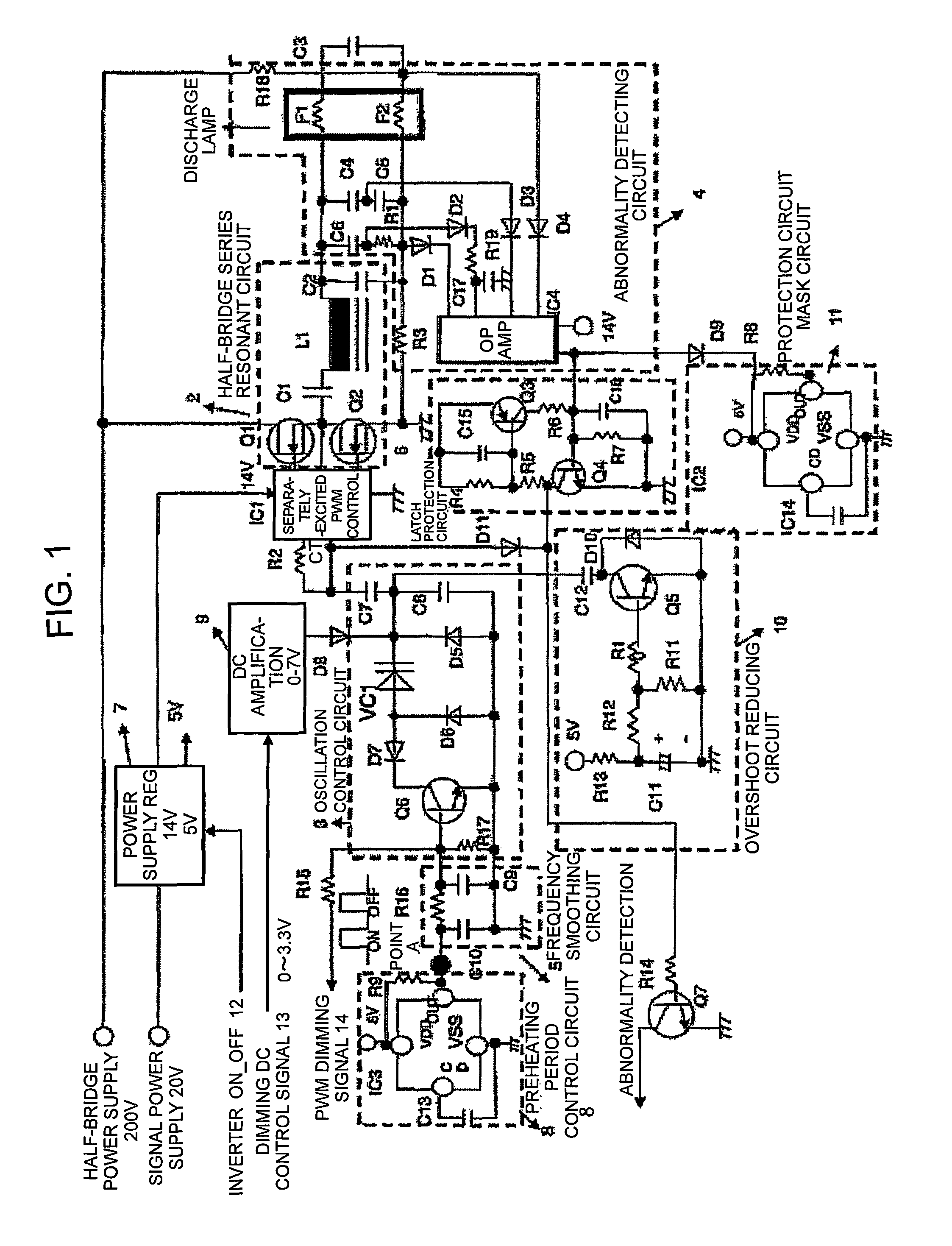
[0043]A first embodiment of the present invention is described below on the basis of FIGS. 1 and 5 to 11. FIG. 1 is a diagram illustrating a circuit configuration of the first embodiment. A separately-excited PWM control integrated circuit IC1 is connected with an oscillation control circuit 3, a half-bridge series resonant circuit 2, and a latch protection circuit 6. The oscillation control circuit 3 includes a capacitor C8 for determining an oscillation frequency, and a variable capacitance diode VC1 for dimming, and an anode of the variable capacitance diode VC1 is connected with a switching transistor Q6 for ON-OFF switching. Also, one end of the capacitor C8 is connected with an overshoot reducing circuit 10 (soft start circuit for the case of inverter activation). Further, a base of the transistor Q6 is connected with a frequency smoothing circuit 5 for making a gradual transition of a frequency upon transition from a preheating period to lighting.

[0044]The half-bridge series ...


PUM


Abstract

A discharge lamp lighting device has an oscillation control circuit for determining a frequency with time constant of R and C, a L-C series resonant circuit connected to a half bridge or full bridge operating at the frequency and a circuit in which one end of hot cathodes at both ends of a hot cathode type discharge tube are respectively connected to both ends of a resonant capacitor. A capacitor is further connected in series to other ends of filaments at both ends of the discharge tube for lighting. Dimming of tube current is achieved by changing the oscillation frequency with a DC dimming control voltage by use of a variable capacitor or diode for determining the frequency of the oscillation control circuit. By simultaneously changing the tube current and a filament current of the discharge lamp, the tube current is decreased upon dimming and the filament current is increased.

Description

TECHNICAL FIELD[0001]The present invention relates to a hot cathode type discharge lamp lighting device capable of performing stable discharge operation and nonstep dimming control.BACKGROUND ART[0002]There has conventionally been provided a discharge lighting device capable of performing dimming control of a hot cathode type discharge lamp such as a fluorescent lamp. In the case of dimming, as a tube current is decreased (dimming level is increased), a filament temperature is decreased, and as the tube current is further decreased, discharge cannot be maintained, which in turn causes moving striations and flickering.[0003]A conventional device addressing such a problem is described in, for example, Patent document 1. As illustrated in FIG. 13, the conventional device is configured to include four power supplies including an inverter power supply 1 for lighting, a DC-DC power supply 3 for lighting, a DC-DC power supply 4 for preheating, and an inverter power supply 2 for preheating ...

Claims


Application Information

Patent Timeline
Patent Type & Authority Patents(United States)
IPC IPC(8): H05B41/36
CPCH05B41/3927
Inventor KONISHI, HIROFUMI
Owner TABUCHI ELECTRIC CO LTD
Learn More