Oscillator device comprising a thermally-controlled piezoelectric resonator

a piezoelectric resonator and oscillator technology, which is applied in the direction of oscillator generators, piezoelectric/electrostrictive/magnetostrictive devices, piezoelectric/electrostriction/magnetostriction machines, etc., can solve the problem of large power consumption and long warm-up time, prior art crystal oscillator devices have some problems, and certain amount of heat is susceptible to radiating. to achieve the effect of reducing

Active Publication Date: 2011-10-11
MICRO CRYSTAL
View PDF10 Cites 15 Cited by
  • Summary
  • Abstract
  • Description
  • Claims
  • Application Information

AI Technical Summary

Benefits of technology

[0010]It is therefore an object of the present invention to provide a crystal oscillator device, which can be made small enough to be compatible with surface mounting techniques (SMD), and which has reduced power consumption and a resonator frequency that is more stable in case of changes in the ambient temperature.
[0015]According to the present invention, the heating unit is implemented in the IC chip. An advantage of this arrangement is that the piezoelectric resonator element and the heating unit are located close to each other. This feature contributes to reducing the magnitude of deviations from the set-point temperature of the device.
[0016]According to a particular embodiment of the present invention, oscillation circuitry is implemented in the integrated-circuit chip along with the heating unit. In this case, the piezoelectric resonator element is preferably attached to the active surface of the integrated-circuit chip in such a way as to form direct electrical connections with the oscillation circuitry. This arrangement allows dispensing with leads for connecting the piezoelectric resonator element and the oscillation circuitry. Thermal losses from heat conduction are therefore kept at a minimum.
[0017]According to another particular embodiment of the present invention, the temperature sensor is implemented in the integrated-circuit chip along with the heating unit (and possibly with oscillation circuitry as well). An advantage of this particular embodiment is that as the temperature sensor and the piezoelectric resonator element are located close to the heating unit, the crystal oscillator device can react very fast to any change in temperature.

Problems solved by technology

However, it also has the disadvantage of large power consumption and long warm-up time.
However, such prior art crystal oscillator devices have some problems.
As the piezoelectric element lies directly under the cover, a certain amount of heat is susceptible to radiate from the cover to the crystal element or vice versa.
This can lead to a delay before the temperature control circuit reacts.
Furthermore, once the temperature control has reacted, it takes time for the heat produced by the heater to reach the piezoelectric resonator unit.
It follows that there is a risk that the temperature of the piezoelectric resonator unit will deviate substantially from the set-point temperature of the device.
Therefore, a really stable oscillation can not be guaranteed.

Method used


Image

  • Oscillator device comprising a thermally-controlled piezoelectric resonator
  • Oscillator device comprising a thermally-controlled piezoelectric resonator
  • Oscillator device comprising a thermally-controlled piezoelectric resonator

Examples


Embodiment Construction

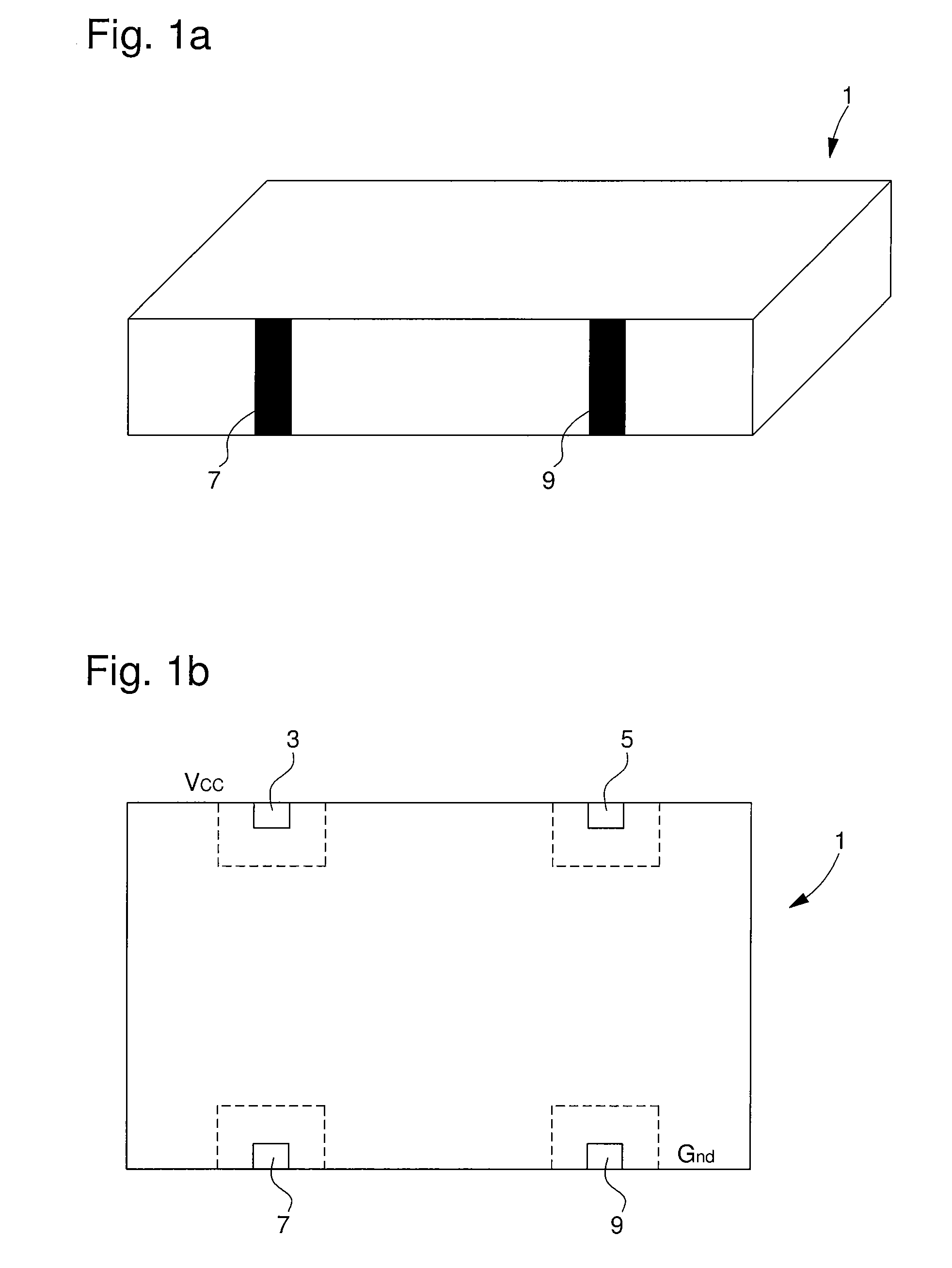
[0025]FIGS. 1a and 1b show a ceramic case 1 adapted to package a crystal oscillator device according to the present invention. The illustrated ceramic case is of the surface mounted (SMD) type. The case 1 can have very small dimensions. For example, the case can be the same size as a standard MCSO. That is 14 millimetres long, 9 millimetres wide and 3.2 millimetres high. As more clearly illustrated in the schematic view of FIG. 1b, the case 1 carries four external electrodes (or pins) 3, 5, 7 and 9. These electrodes are arranged to connect the components of the crystal oscillator device inside the case, to an outside circuit (not shown) through the base or the sides of the case. Electrode 3 is arranged to be connected to the supply voltage (Vcc) and electrode 9 is arranged to be connected to ground (Gnd). In a known manner, electrode 7 is arranged to be connected to a control voltage which allows controlling the oscillation frequency. Finally, electrode 5 is the frequency output fro...


PUM


Abstract

The crystal oscillator device includes an air-tight case (1) forming a vacuum chamber (23), a piezoelectric resonator element (11), oscillation circuitry, a temperature sensor, and a heating unit implemented in an integrated-circuit (IC) chip (13) with an active surface (13a). The piezoelectric resonator element (11) and the oscillation circuitry are connected together to form an oscillation circuit. Furthermore, the temperature sensor and the heating unit are enclosed in the vacuum chamber (23) with the piezoelectric resonator element (11).The piezoelectric resonator element is attached in a heat conductive manner to the active surface (13a) of the integrated-circuit chip (13) in such a way that the IC chip provides mechanical support for the piezoelectric resonator element.

Description

FIELD OF THE INVENTION[0001]The invention relates to a small-sized oscillator device comprising a piezoelectric resonator element. The invention more particularly relates to such an oscillator device capable of maintaining its piezoelectric resonator element at a substantially constant temperature.BACKGROUND OF THE INVENTION[0002]Small-sized crystal oscillator devices are most often used for making reference frequency generators in particular for electronic equipment, in numerous fields such as horology, information technology, telecommunications, GPS, and the medical field.[0003]Small-sized crystal oscillator devices are often (but not necessarily) SMDs (Surface Mounted Devices). A small-sized surface-mount crystal oscillator device is known, which comprises a container for surface mounting, a piezoelectric resonator element (the crystal), and an integrated circuit chip (IC chip) connected to the piezoelectric resonator element so as to form an oscillation circuit. The IC chip and ...

Claims


Application Information

Patent Timeline
Patent Type & Authority Patents(United States)
IPC IPC(8): H04L1/04H03B5/32H01L41/053
CPCH03L1/028H03L1/04
Inventor NAVET, JEAN-MARC
Owner MICRO CRYSTAL
Why Eureka
Try Eureka