
Method and device for measuring emissions of gaseous substances to the atmosphere using scattered sunlight spectroscopy

a gaseous substance and emission measurement technology, applied in the field of gaseous substance emission measurement to the atmosphere using scattered sunlight spectroscopy, can solve the problems of only measuring emission, power consumption of the device, and not being able to determine unambiguously the clean air background

Active Publication Date: 2011-10-11
GALLE BO
View PDF7 Cites 1 Cited by
  • Summary
  • Abstract
  • Description
  • Claims
  • Application Information

AI Technical Summary

Benefits of technology

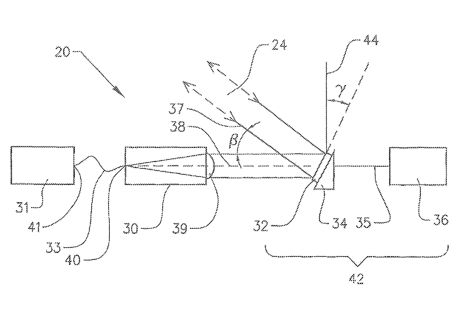
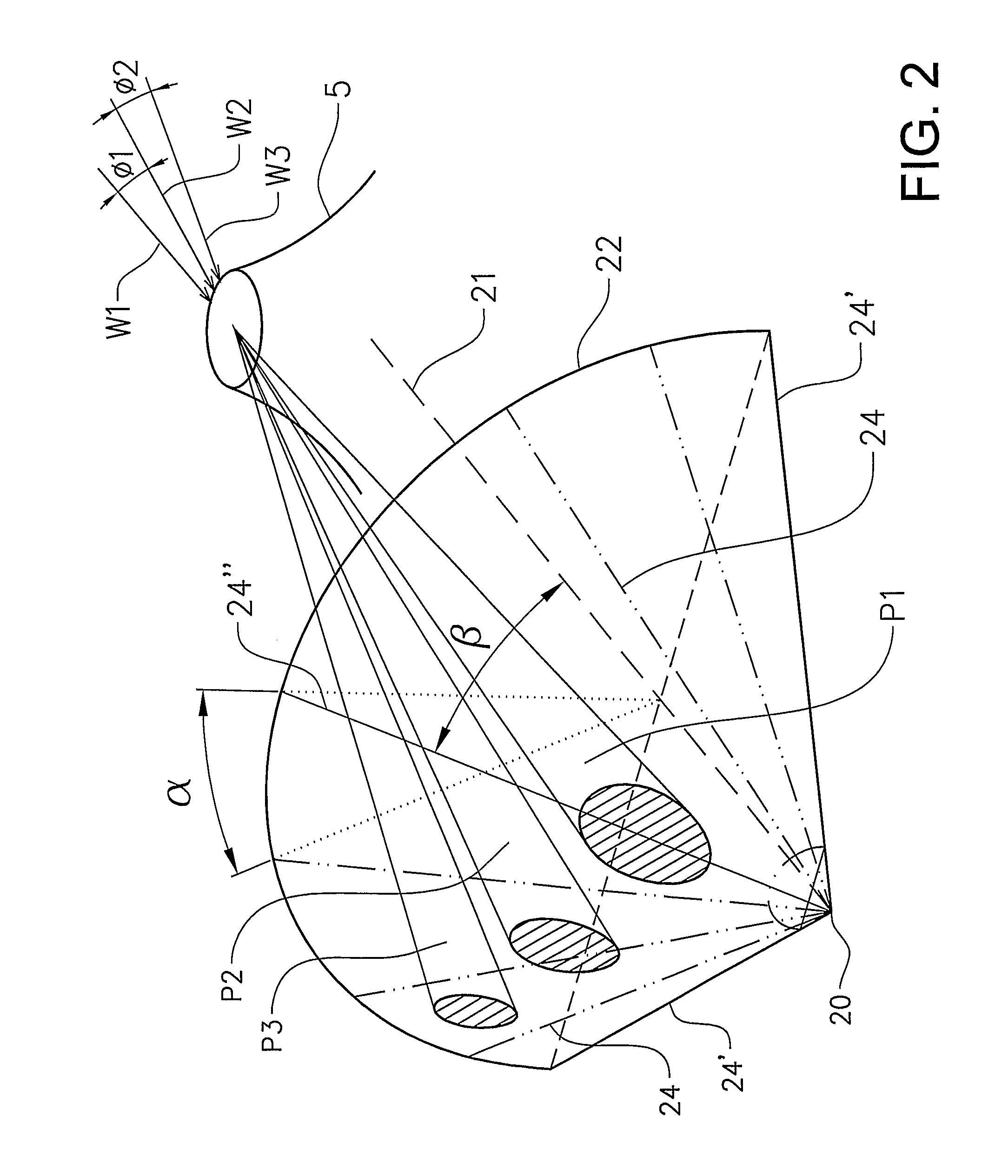
[0019]Such a scanning layer is capable of being directed towards an emission source and partly surrounding the source resulting in several advantageous effects. One advantage is that it increases the wind direction interval within which a reliable measurement can be performed. A consequence of this is that a wider range of wind directions can be covered by a single instrument, or alternatively that a smaller number of stationary measuring devices are required to cover all possible wind directions around an emission source. Another advantage is that the distance between the measuring device and the location where an emission plume is scanned is decreased which improves the reliability of the measurement as the previously described scattering effects are reduced. This is of particular importance when the wind direction deviates considerably from a direction right above the place where the measuring device is positioned.

Problems solved by technology

The small size and power consumption of the device made possible measurements in hitherto inaccessible areas and situations.
However, this also means that the emission can only be measured when the wind direction is such that the gas plume from the volcano is passing over the instrument within a certain angular interval around zenith.
Typically it will not be able to determine unambiguously the clean air background below the plume.
An effect of this is that it becomes difficult to evaluate the integrated concentration in the gas plume which leads to an unreliable determination of the amounts of emissions in the plume.
Another problem related to this measurement strategy is caused by scattering of light in the lower part of the atmosphere.
This part of the recorded light has never passed the gas plume and thus causes a “diluted” spectrum, giving rise to an underestimation of the gas content in the plume.
This problem gets worse the more aerosols (haze, particles, ash, rain, etc.) there is in the lower atmosphere.
It also gets worse when the plume is intersected at high zenith angles (close to the horizon) and when the distance between the instrument and the gas plume is long.

Method used


Image

  • Method and device for measuring emissions of gaseous substances to the atmosphere using scattered sunlight spectroscopy
  • Method and device for measuring emissions of gaseous substances to the atmosphere using scattered sunlight spectroscopy
  • Method and device for measuring emissions of gaseous substances to the atmosphere using scattered sunlight spectroscopy

Examples


Embodiment Construction

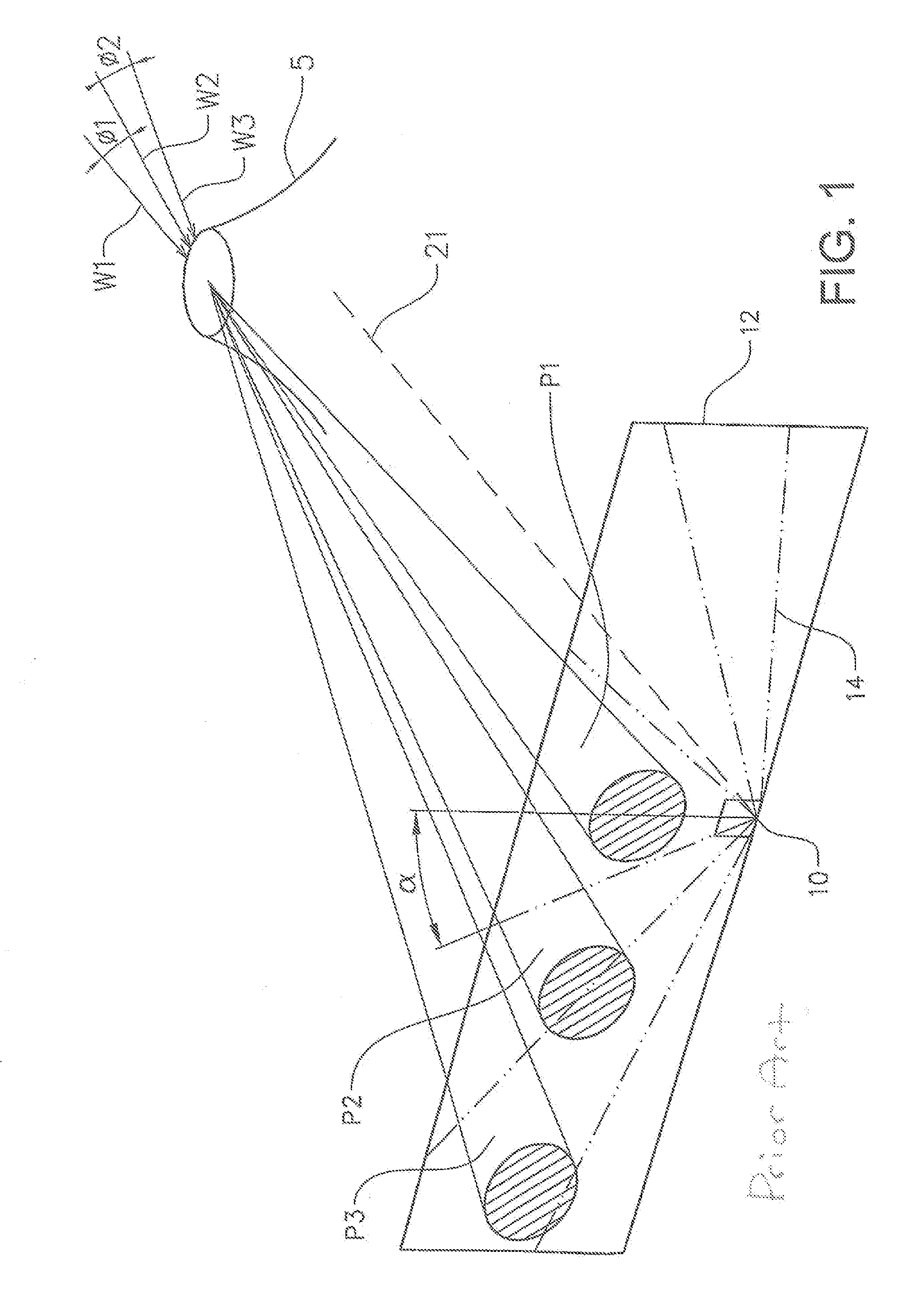
[0036]FIGS. 1 and 2 show a 3-d representation of the measurement strategies for the prior art and the present invention, respectively. FIG. 1 gives a principal illustration of the use of a prior art optical measuring device 10 in the form of a scanning mini-DOAS in measurements of a gas emission from a source in the form of a volcano 5. In particular, FIG. 1 illustrates the effect of different plume directions relative to the location of the measuring device 10. Three different plumes P1, P2 and P3 represent three different wind directions W1, W2 and W3. The first wind direction W1 is directed from the gas emission source 5 towards the measuring device 10 resulting in that the corresponding plume P1 passes right above the measuring device 10. The second wind direction W2, and thus the direction of the second plume P2, exhibit an angle Φ1 relative to the direction of W1 and P1 such that the second plume P2 passes above the measuring device 10 somewhat at the side. The third wind dire...


PUM


Abstract

Methods for measuring emissions of gaseous substances to the atmosphere using scattered sunlight spectroscopy and an optical measuring device are disclosed in which the device includes a telescopic member defining a field-of-view of the optical measuring device and a scanner for controlling variation of the direction of the field of view to scan a predetermined layer of the atmosphere, the method comprising scanning the field-of-view to scan the predetermined layer of the atmosphere in the form of at least a part of a cone having its apex positioned at the optical measuring device and having a cone angle β. Optical measuring devices themselves are disclosed.

Description

FIELD OF THE INVENTION[0001]The present invention relates to a method for measuring emissions of gaseous substances to the atmosphere using scattered sunlight spectroscopy and an optical measuring device. The present invention also relates to an optical measuring device for use in such a method.BACKGROUND OF THE INVENTION[0002]Gaseous substances are constantly emitted to the atmosphere from both anthropogenic sources, such as vehicles and industries, and natural sources, such as volcanoes. Many of these substances have an effect on human health and / or on the global climate, the protective ozone layer in the stratosphere or other environmental effects. In order to study such effects and to quantify different sources etc., it is important that there are suitable equipment and methods available for measuring emissions and flux of such gaseous substances. The principles of some different methods are described in e.g. WO 02 / 04902.[0003]Measurement of gases from volcanoes are important no...

Claims


Application Information

Patent Timeline
Patent Type & Authority Patents(United States)
IPC IPC(8): G01J3/28
CPCG01J3/02G01J3/021G01J3/0289G01J3/4412G01N21/33G01N2021/1795G01N2021/3531G01N2201/0616G01V8/14G01V9/007
Inventor GALLE, BO
Owner GALLE BO
Learn More