Method and apparatus for liquid cooling computer equipment

a computer equipment and liquid cooling technology, applied in the field of liquid cooling apparatus, liquid cooling system, an apparatus, and a cooling system, can solve the problems of compounding energy conversion inefficiencies, increasing the cost of cooling a high-performance computing center, and increasing the cost of operating the computing center

Active Publication Date: 2011-10-11
ORACLE INT CORP
View PDF22 Cites 39 Cited by
  • Summary
  • Abstract
  • Description
  • Claims
  • Application Information

AI Technical Summary

Benefits of technology

[0016]Another advantage of using a low pressure liquid cooling circuit is that liquid connections are less prone to leakage and are consequently more reliable. Low pressure liquid connections are also less expensive than high pressure fluid connections.
[0018]According to other aspects of the cooling system, a reservoir may be provided that contains a liquid that is pumped to a discharge port, or weir, located above the computer equipment rack. A coolant feed manifold may receive liquid from the weir and directs the liquid by gravity flow to fill at least one branch tank that is disposed above at least one computer equipment card. The branch tank may be open to atmospheric pressure or otherwise maintained at low pressure. Similarly, the drain branch may also be simply maintained at atmospheric pressure. In this way, a balanced flow of coolant is provided to the computer equipment that is not effected by changes in the number of components to be cooled or other variations in the system.

Problems solved by technology

As the number of computer components provided in electronics enclosures or racks increases, problems relating to cooling the components also increases.
The cost of cooling a high-performance computing center increases the cost of operating the computing center.
Energy conversion inefficiencies are compounded by the use of air flow fans, heat exchanger grids and compressors.
Air flow fans used to circulate air also consume power and generate additional heat that must be removed from the system.
The cost of operating a high pressure liquid system may be substantial in a high performance computing environment.
Cooling such a large number of computer components consumes power for cooling the components on the racks and adds to the total cost of operating the data center.
Adding and removing modules from the system may affect the head pressure or flow of water through the system.
Higher pressure systems may stress liquid connections and be more prone to development of leaks.
Higher cost components of a high pressure cooling circuit increase the cost of the cooling system.

Method used


Image

  • Method and apparatus for liquid cooling computer equipment
  • Method and apparatus for liquid cooling computer equipment
  • Method and apparatus for liquid cooling computer equipment

Examples


Embodiment Construction

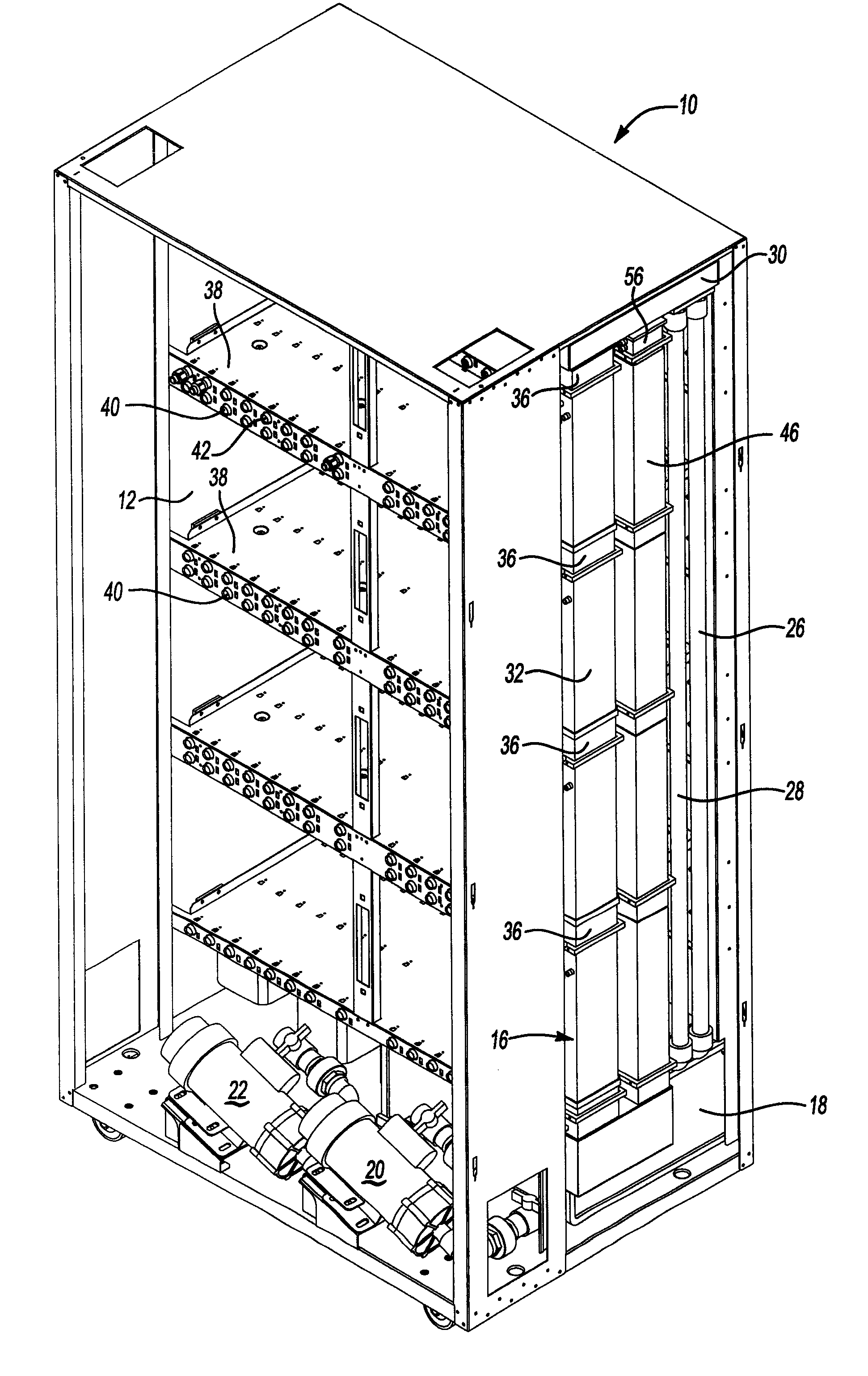
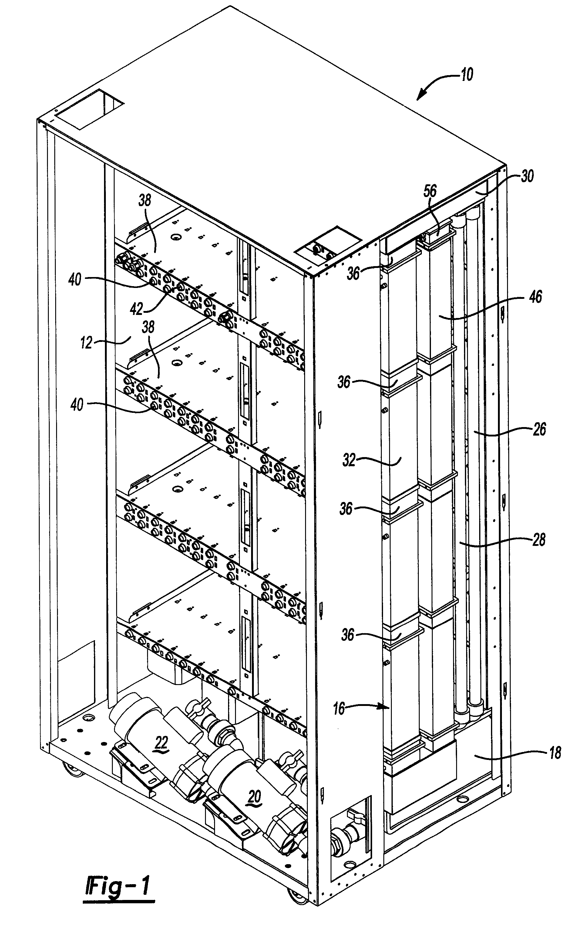
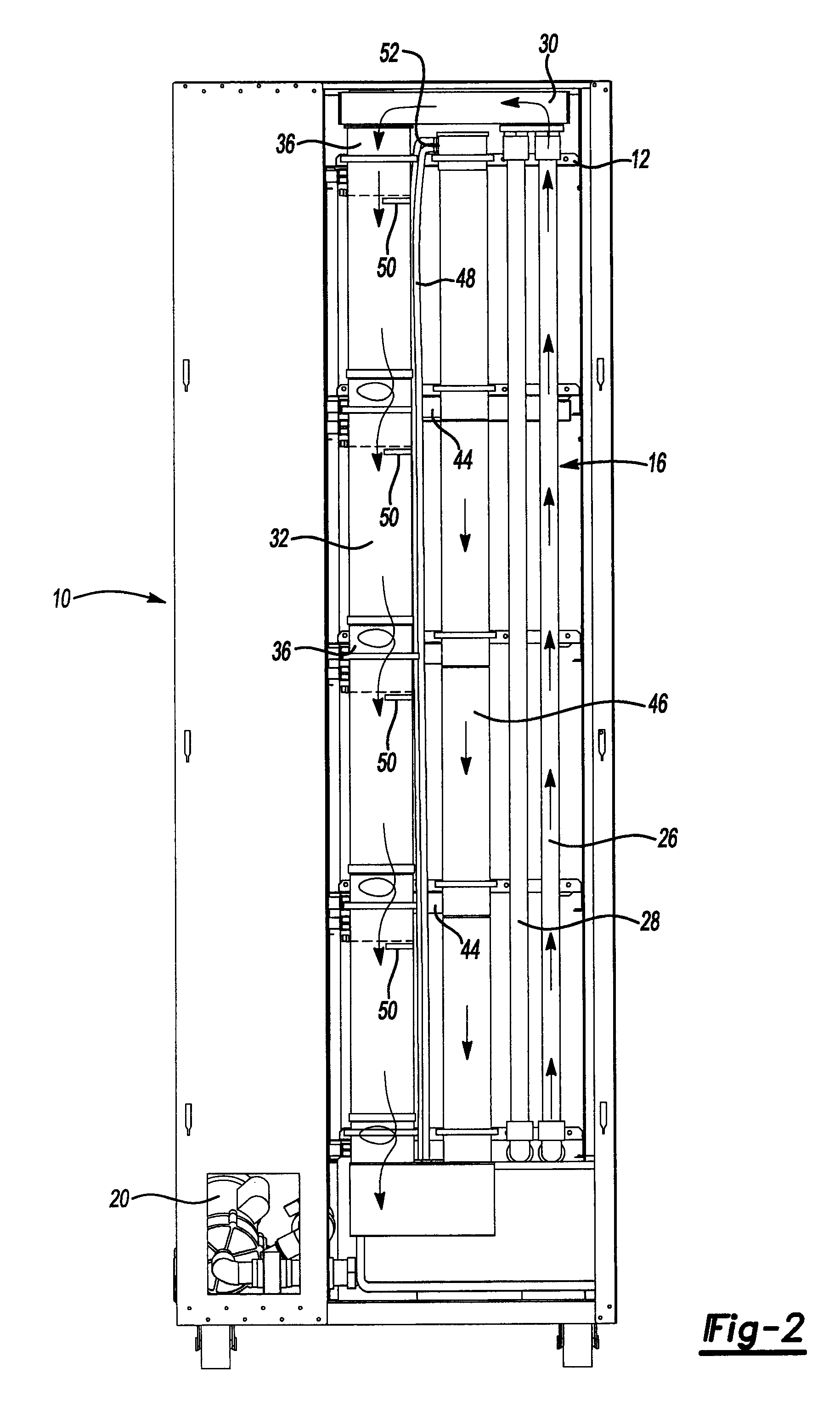
[0031]Referring to FIGS. 1-4, an enclosure 10 is shown in FIGS. 1 and 2 that encloses a rack 12 for computer components. A cooling system 16 is shown in association with the enclosure 10 that is used to cool computer components (not shown in FIGS. 1 and 2) that are disposed on the rack 12.

[0032]The cooling system 16 includes a reservoir 18 for a liquid, such as water or another coolant. A pump 20 draws liquid from the reservoir 18. An auxiliary pump 22 is provided in the event that the pump 20 fails or requires service and thereby assures that an adequate supply of coolant is circulated through the cooling system 16. The pump 20 pumps the liquid through a supply pipe 26 upwardly to a point near the top of the enclosure 10. An auxiliary supply pipe 28 receives the cooling liquid from the auxiliary pump 22, if necessary. The supply pipe 26 provides water to a discharge port chamber 30 at the outlet end of the supply pipe 26. The auxiliary supply pipe 28 also opens into the discharge p...


PUM


Abstract

A cooling system for cooling computer component with a liquid provided at atmospheric pressure, or low pressure, that flows through channel defined in the computer component. The liquid is pumped from a reservoir to a discharge port, or weir, that is located above the computer component. The liquid flows through an in-feed manifold to diverters that direct the liquid into in-feed tanks located above a row of the computer component. The liquid flows through the channels and flow control orifices to a drain that returns the liquid to the reservoir.

Description

BACKGROUND OF THE INVENTION[0001]1. Field of the Invention[0002]The present invention relates to a cooling system, a method, and an apparatus for liquid cooling an article of computer equipment.[0003]2. Background Art[0004]Computer equipment is generally assembled within an enclosure or to an open rack. Computer components, such as server blades, power supplies, switches and data storage modules, may be added or removed at will by a user to provide scalability for the system and field replacement of circuit components.[0005]Computer components generally require cooling to operate at peak efficiency. Cooling for computer components is normally provided by circulating air that is driven by fans that circulate around the computer components. The air is then cooled by flowing through heat exchangers that are disposed adjacent to the computer components. Alternatively, the air circulating through the computer components may be cooled by the air conditioning system of a data center. As th...

Claims


Application Information

Patent Timeline
Patent Type & Authority Patents(United States)
IPC IPC(8): H05K7/20
CPCH05K7/20645H05K7/20781G06F1/20G06F2200/201
Inventor OSTWALD, TIMOTHY C.PLUTT, DANIEL J.MANES, JOSEPH P.
Owner ORACLE INT CORP
Why Eureka
Try Eureka