
Asynchronous dual-queue interface for use in network acceleration architecture

a network acceleration and dual-queue interface technology, applied in the field of network acceleration, can solve the problems of limiting the life-time of such solutions, limiting the performance benefits and performance of such solutions, and so as to preserve protocol implementation flexibility, maintain protocol modification, and achieve the effect of sacrificing performance and efficiency

Inactive Publication Date: 2011-10-11
INT BUSINESS MASCH CORP
View PDF13 Cites 11 Cited by
  • Summary
  • Abstract
  • Description
  • Claims
  • Application Information

AI Technical Summary

Benefits of technology

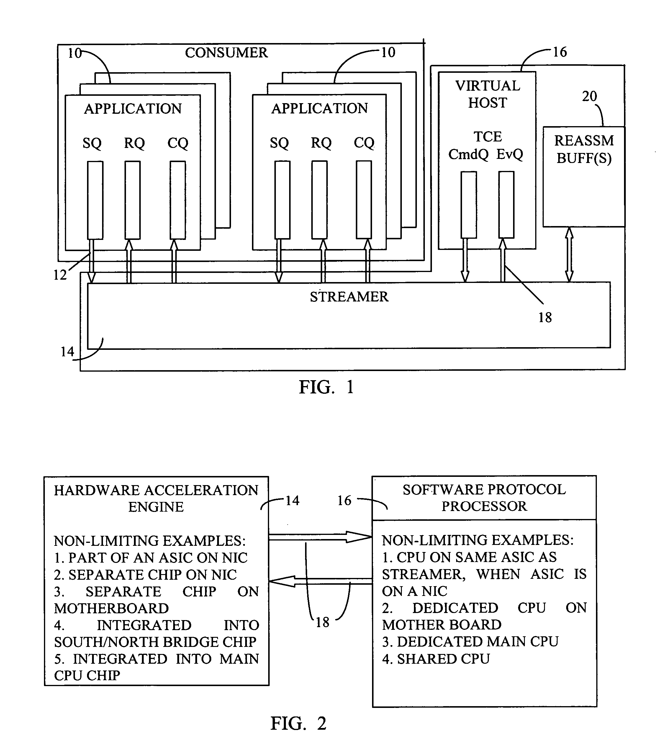
[0008]In accordance with a non-limiting embodiment of the invention, heavy data intensive operations are separated from the protocol control. Data processing may include “fast path” execution (defined in the description below) performed by a dedicated hardware acceleration engine, whereas the protocol control operations may be carried out by software. The split of functions between software and hardware is done in such way that allows asynchronous and independent operation of the data processing (hardware) and the protocol control (software). There is a “loose” coupling of the software and hardware components. The invention preserves flexibility in protocol implementation and is capable of sustaining protocol modification, without sacrificing performance and efficiency.

Problems solved by technology

One challenge is that all data processing operations must be handled efficiently, while at the same time, the protocol implementation must be flexible.
Another challenge is the ability to adapt to increases in main CPU speed, main memory bandwidth and latency.
Such a solution is generally limited by the embedded CPU capabilities, which typically lag behind the main CPU technology for several generations.
This limits the performance benefits and life-time of such solutions.
This adds additional latency, makes implementation difficult and increases the cost of the overall solution.
However, this lacks flexibility in protocol processing, which as mentioned previously, is particularly important in TCP.

Method used


Image

  • Asynchronous dual-queue interface for use in network acceleration architecture
  • Asynchronous dual-queue interface for use in network acceleration architecture
  • Asynchronous dual-queue interface for use in network acceleration architecture

Examples


Embodiment Construction

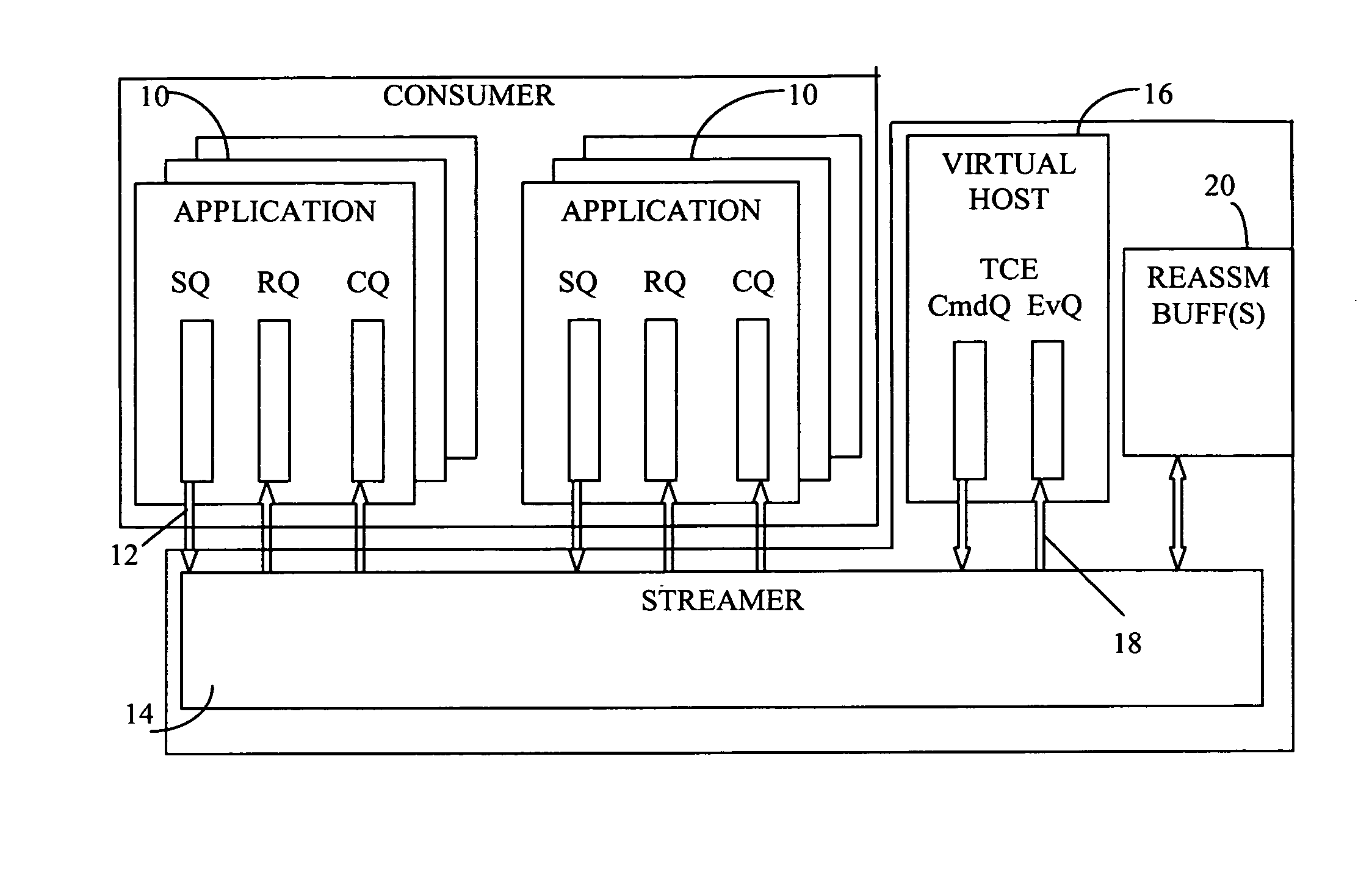
[0015]Reference is now made to FIG. 1, which illustrates a network acceleration architecture in accordance with an embodiment of the present invention.

[0016]The network acceleration architecture may include consumer applications 10, which may run on a main CPU complex. The consumer applications 10 may use asynchronous queue based interface(s) 12 to submit work requests to a hardware acceleration engine 14, also referred to as a streamer 14. The interface(s) 12 may be in accordance with the RDMA verb specification.

[0017]As is known in the art, RDMA uses an operating system programming interface, referred to as “verbs”, to place work requests (WRs) onto a work queue. In brief, queue pairs may be used to transfer messages to the streamer 14 (e.g., memory regions in the streamer 14). Each queue pair may include a send work queue (SQ) and a receive work queue (RQ). For example, the consumer application 10 may generate work requests, which are placed onto a work queue as work queue elemen...


PUM


Abstract

A method for receiving data in a network acceleration architecture for use with TCP (transport control protocol), iSCSI (Internet Small Computer System Interface) and RDMA (Remote Direct Memory Access) over TCP, including providing a hardware acceleration engine, called a streamer, adapted for communication with and processing data from a consumer application in a system that supports TCP, iSCSI and RDMA over TCP, providing a software protocol processor adapted for carrying out TCP implementation, the software control processor being called a TCE (TCP Control Engine), and providing an asynchronous dual-queue interface for exchanging information between the streamer and TCE, wherein the streamer and TCE are adapted to operate asynchronously and independently of one another.

Description

FIELD OF THE INVENTION[0001]The present invention relates generally to network acceleration, and more particularly to a network acceleration architecture which allows efficient iSCSI (Internet Small Computer System Interface) and RDMA (Remote Direct Memory Access) acceleration, preserves flexibility of TCP (transport control protocol) implementation, and adapts to increasing main CPU (central processing unit) speed, memory bandwidth and latency.BACKGROUND OF THE INVENTION[0002]RDMA is a technique for efficient movement of data over high-speed transports. RDMA enables a computer to directly place information in another computer's memory with minimal demands on memory bus bandwidth and CPU processing overhead, while preserving memory protection semantics. RNIC is a Network Interface Card that provides RDMA services to the consumer. The RNIC may provide support for RDMA over TCP.[0003]RNIC can serve as an iSCSI target or initiator adapter. “Initiator” refers to a SCSI command requester...

Claims


Application Information

Patent Timeline
Patent Type & Authority Patents(United States)
IPC IPC(8): G06F15/167G06F15/16
CPCH04L49/90H04L49/9063
Inventor BIRAN, GIORAMACHULSKY, ZORIKMAKHERVAKS, VADIMRECIO, RENATO JOHNSATRAN, JULIANSHALEV, LEAHSHIMONY, ILAN
Owner INT BUSINESS MASCH CORP
Learn More