Electrode unit for prismatic battery, prismatic battery, and method of manufacturing electrode unit for prismatic battery

a technology of prismatic batteries and electrode units, which is applied in the direction of sustainable manufacturing/processing, cell components, flat cell grouping, etc., can solve the problems of reducing the effect of reducing the internal resistance of the battery, increasing the length d of the side, and reducing the internal resistance value of the battery, so as to improve the output of the battery and suppress the internal resistance value. , the effect of improving the degree of freedom

Active Publication Date: 2011-10-18
PANASONIC EV ENERGY CO LTD
View PDF6 Cites 0 Cited by
  • Summary
  • Abstract
  • Description
  • Claims
  • Application Information

AI Technical Summary

Benefits of technology

According to the present invention, a reduction in the current collection effect hardly occurs even in regions near the centers of both electrode plates because the regions are close to the core material exposed portions, that is, the respective current collectors. As a result, the present invention can also suppress the battery internal resistance value to a small value, contributing to improvement in the output of the battery. In addition, the present invention also contributes to improvement in the degree of freedom of the size of the positive electrode plate and the negative electrode plate.
Further, the present invention can improve the degree of freedom about the outer shape in conjunction with the improvement in the degree of freedom of the size of the positive electrode plate and the negative electrode plate.

Problems solved by technology

Incidentally, for the prismatic battery proposed in the above-described Patent Document 1 (Japanese Patent Application Laid-open No. 2001-93508), a technology is also described in which L>D and L≦4D are established where the length of the side provided at the lead portion is L and the length of the side perpendicular to that is D.” In other words, a problem of the technology is that the current collection ability by the current collector joined to one end surface of the electrode plate decreases with an increase in the length D of the side perpendicular to the side provided at the lead portion, with the result that “the effect of reducing the battery internal resistance” is reduced.
A problem of the technology described in Patent Document 2 is that the current collection ability by the current collector joined to one end surface of the electrode plate also decreases when the ratio of electrode plate width dimension to electrode plate height dimension is 0.67 or more, with the result that “the effect of reducing the battery internal resistance” is reduced.

Method used


Image

  • Electrode unit for prismatic battery, prismatic battery, and method of manufacturing electrode unit for prismatic battery
  • Electrode unit for prismatic battery, prismatic battery, and method of manufacturing electrode unit for prismatic battery
  • Electrode unit for prismatic battery, prismatic battery, and method of manufacturing electrode unit for prismatic battery

Examples


first embodiment

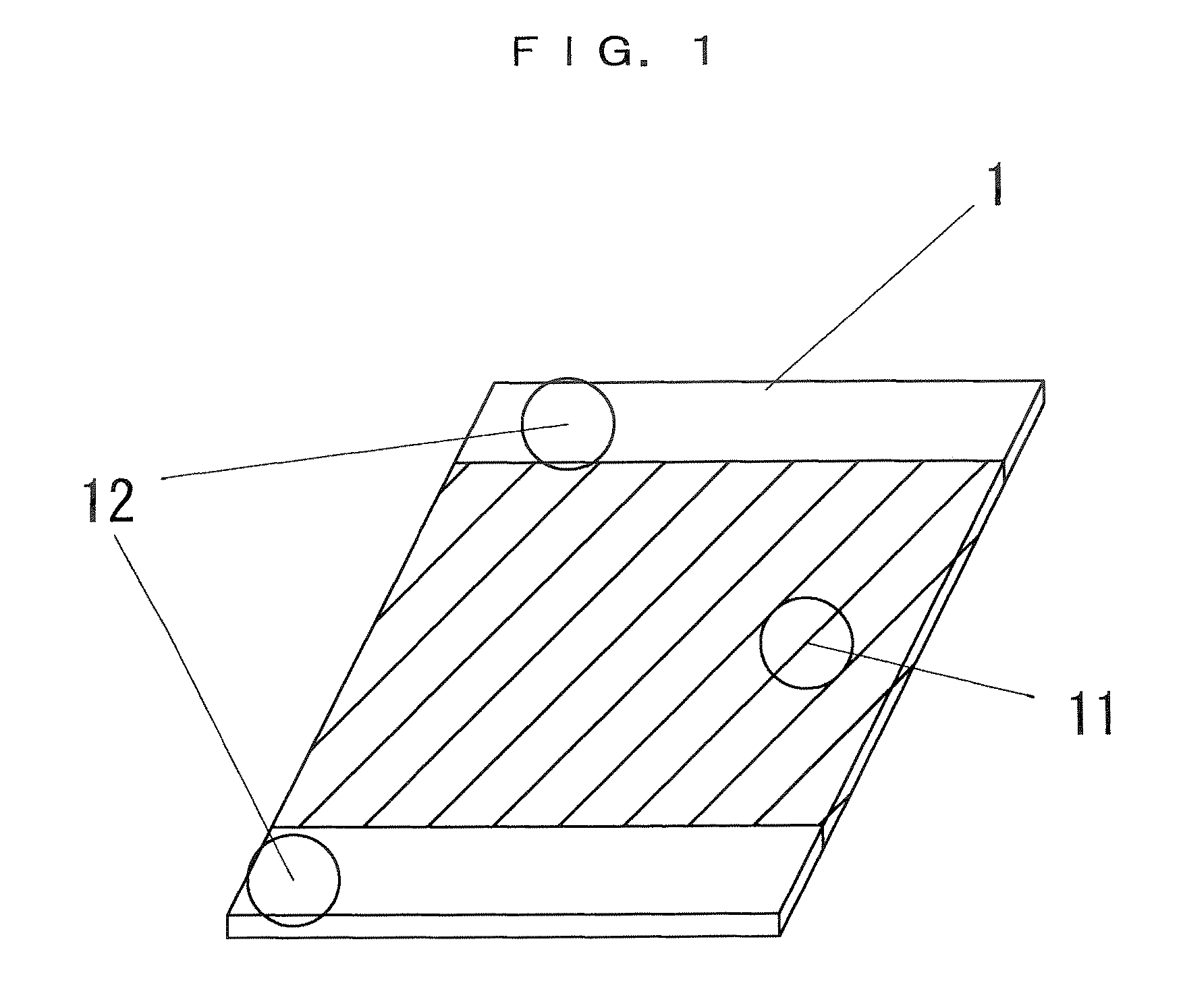
As shown in FIG. 1, a positive electrode plate 1 is formed in an almost rectangular plate-shape and includes an active material filled portion 11 in which an active material containing nickel hydroxide as a main component is filled in a core material, and core material exposed portions 12 in which the active material is not filled formed at two opposite side edges.

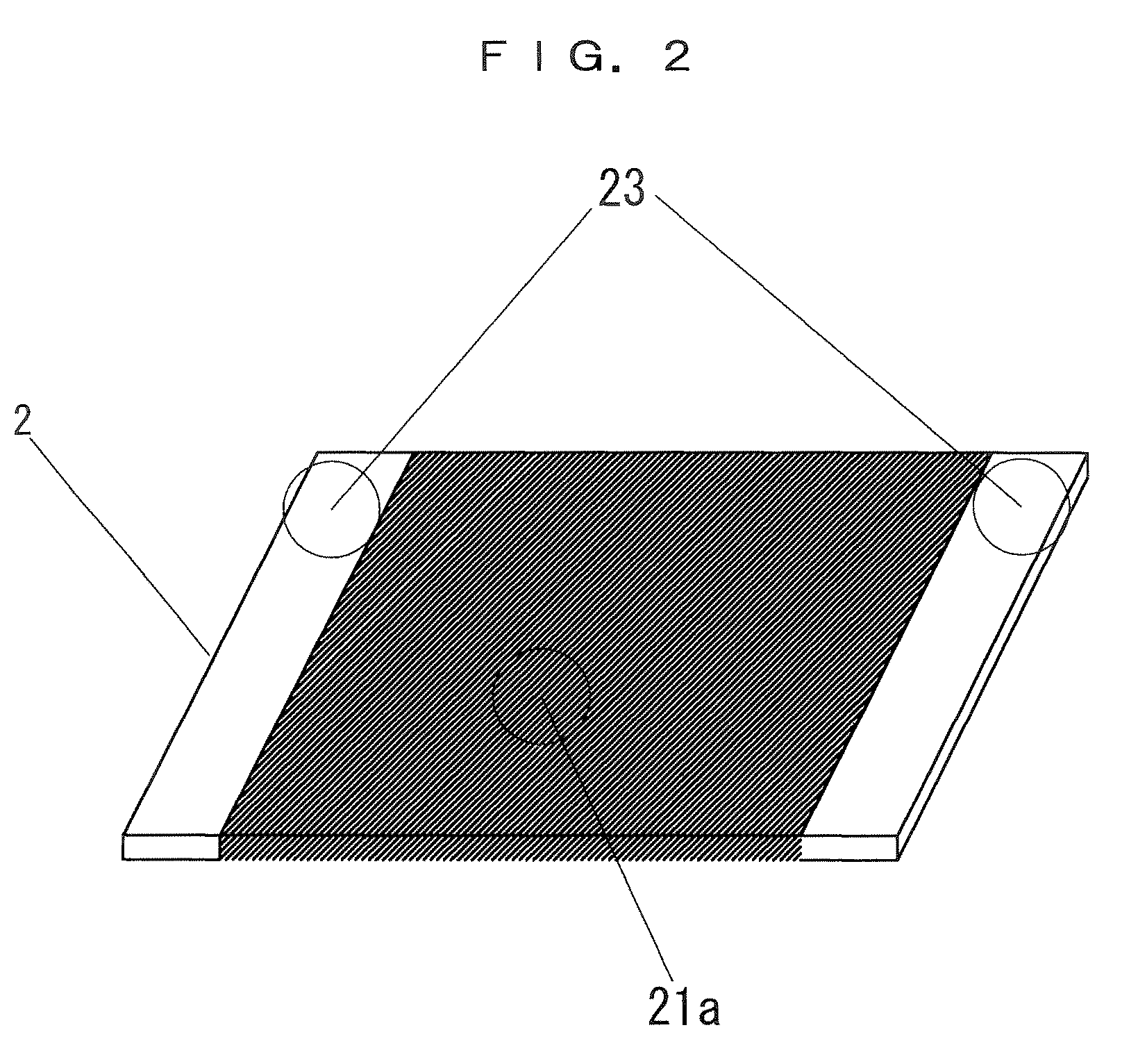
A negative electrode plate 2 is formed from a porous metal plate (punching metal), as shown in FIG. 2, in an almost rectangular plate-shape and includes an active material filled portion 21a in which a paste containing, as a main component, fine particles of a hydrogen absorbing alloy being a negative electrode active material is applied to the porous metal plate, and core material exposed portions 23 in which the active material is not applied to the porous metal plate formed at two opposite side edges.

Note that the negative electrode active material is hydrogen in principle, but the hydrogen absorbing alloy being a main ...

second embodiment

The different points between the first embodiment shown in FIG. 1 to FIG. 5 and a second embodiment shown in FIGS. 6A to 6C are as follows. Namely, the regions of the core material exposed portions 12 and 23 formed in the positive electrode plate 1 and the negative electrode plate 2 are not on the two side edges along a pair of opposite sides but on two side edges adjacent to each other.

As shown in FIG. 6B, a positive electrode plate 1 is provided with core material exposed portions 12 at two adjacent side edges in an inverted-L shape in the drawing. Further, the front and back both surfaces of the positive electrode plate 1 are covered with a separator 3 with the core material exposed portions 12 protruding.

As shown in FIG. 6C, a negative electrode plate 2 is provided with core material exposed portions 23 at two adjacent side edges in an L shape in the drawing opposed to the core material exposed portions 12 of the positive electrode plate 1. Further, the negative electrode plates...

third embodiment

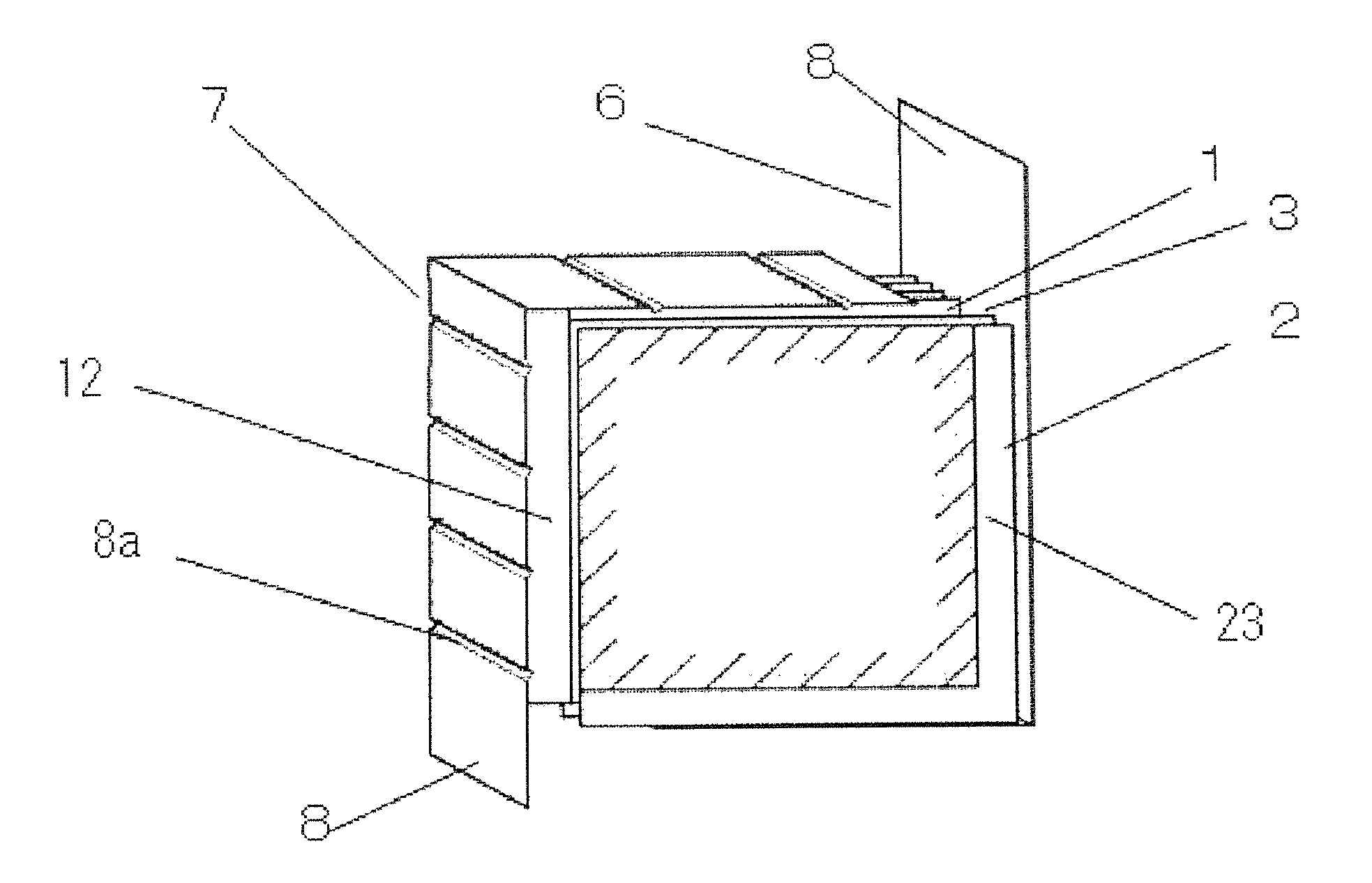
FIGS. 7A to 7C show a third embodiment. The point of the third embodiment different from the second embodiment shown in FIGS. 6A to 6C is that the terminals 8 and 8 for connection extended from the current collectors 7 and 6 are located at face-to-face positions. This embodiment is suitable for the case in which an external connection structure connected to the electrode unit for a prismatic battery according to this embodiment (an external connection device using an electrode unit for a prismatic battery as the power supply) requires the positive electrode and negative terminals facing each other.

Also in this case, the maximum current ability can be exhibited irrespective of the aspect ratios of the positive electrode plate 1 and the negative electrode plate 2 (the ratios between D and L shown in FIGS. 7B and 7C).


PUM

PropertyMeasurementUnit
porosityaaaaaaaaaa
lengthaaaaaaaaaa
widthaaaaaaaaaa

Abstract

To provide an electrode unit for a prismatic battery capable of increasing the output of the battery while suppressing the battery internal resistance value and improving the degree of freedom of the size of the electrode plate. An electrode unit for a prismatic battery including an electrode group in which positive electrode plates and negative electrode plates in an almost rectangular shape are alternately stacked with separators interposed therebetween. In each of the positive electrode plate and the negative electrode plate, core material exposed portions are formed at least on two side edges. The positive electrode plates and the negative electrode plate are stacked such that their core material exposed portions are directed not to overlap each other in the stack direction. The electrode unit for a prismatic battery includes a positive current collector having a shape capable of joining to all of the core material exposed portions of the positive electrode plates constituting the electrode group, and a negative current collector capable of joining to all of the core material exposed portions of the negative electrode plates constituting the electrode group, not in contact with the positive current collector.

Description

BACKGROUND OF THE INVENTION1. Field of the InventionThe present invention relates to an electrode unit for a prismatic battery including an electrode group formed comprising positive electrode plates, negative electrode plates, and separators, a prismatic battery, and a method of manufacturing an electrode unit for a prismatic battery.2. Description of the Related ArtIn recent years, portable information devices such as a cellular phone, note book-sized personal computer and so on have become widespread. Those devices aim for higher performance, reduced weight, and miniaturization. Accordingly, the secondary battery for use in the power supply of the portable information devices is required to have reduced size and weight and increased energy density.On the other hand, for external environment such as considerations to rise in gasoline price and global warming, expectations are raised for an electric vehicle. Besides, a so-called hybrid electric vehicle which uses a gasoline engine ...

Claims


Application Information

Patent Timeline
Patent Type & Authority Patents(United States)
IPC IPC(8): H01M2/26H01M4/02H01M4/13H01M4/131H01M4/133H01M4/139H01M4/24H01M4/32H01M10/05H01M10/0525H01M10/0585H01M10/34H01M50/533H01M50/536
CPCH01M2/263H01M10/0413H01M10/058H01M10/281H01M2/0217H01M10/052Y02P70/54H01M10/345Y02E60/124Y02E60/122Y10T29/49115Y02E60/10H01M50/103Y02P70/50H01M50/536H01M50/533
Inventor KASAHARA, HIDEKIHAYASHI, KIYOSHI
Owner PANASONIC EV ENERGY CO LTD
Why Eureka
Try Eureka