
Method of manufacturing semiconductor device

a manufacturing method and semiconductor technology, applied in semiconductor devices, semiconductor/solid-state device details, electrical devices, etc., can solve the problems of cumn alloy being cumn alloy is difficult to bond to the side surfaces of the groove as compared with the bottom surface, and the alloy film formed on the side surfaces of the groove is excessively reduced in thickness, so as to reduce the amount of excess mn not contributing to the formation of the barrier film

Inactive Publication Date: 2011-10-18
ROHM CO LTD
View PDF5 Cites 3 Cited by
  • Summary
  • Abstract
  • Description
  • Claims
  • Application Information

AI Technical Summary

Benefits of technology

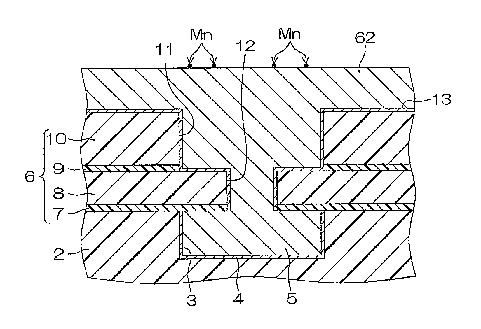
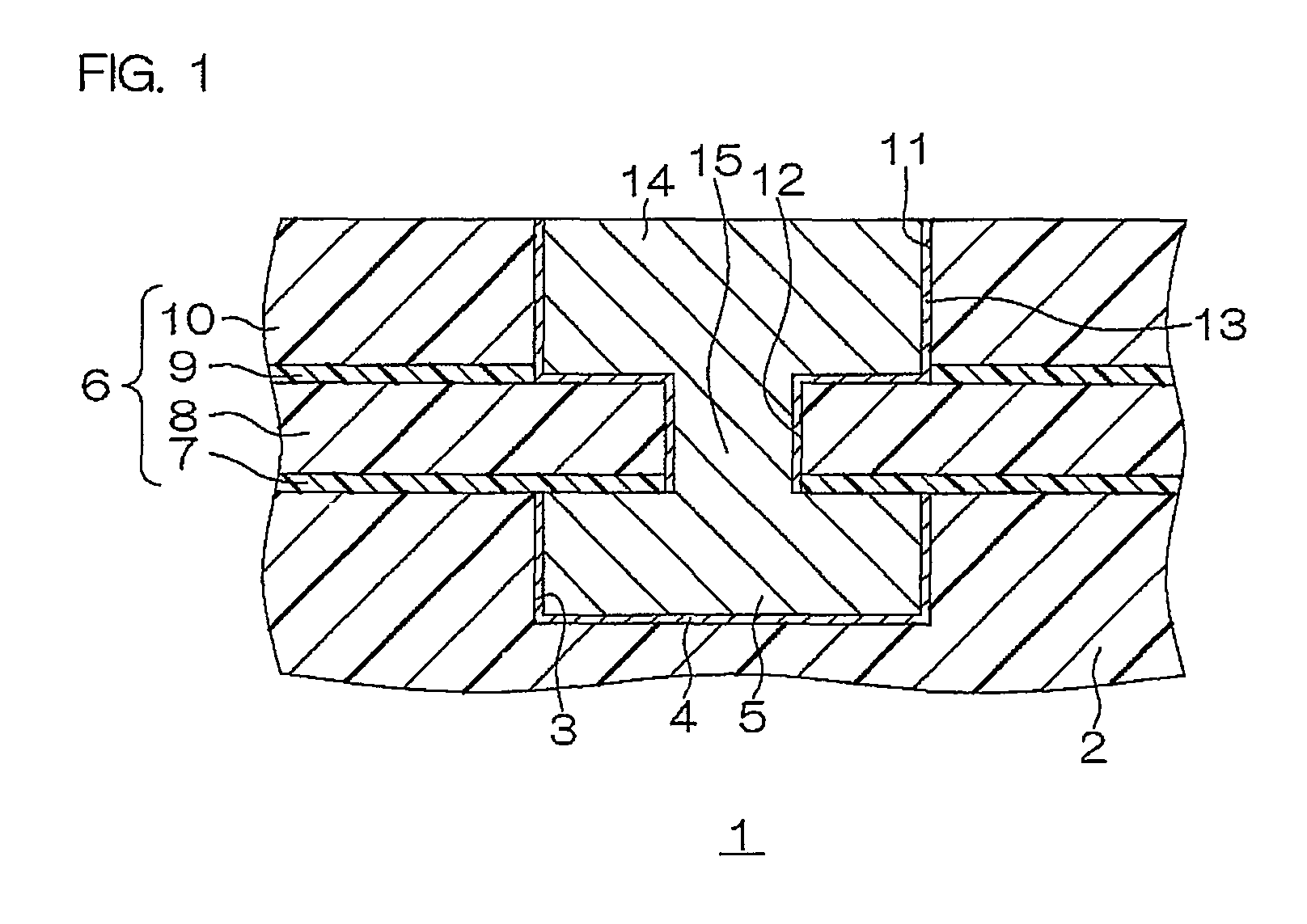
The present invention provides a method of manufacturing a semiconductor device that reduces the amount of Mn remaining in a Cu wire while preventing separation of an alloy film from the side surface of a groove. This is achieved by covering the side surface and bottom surface of the groove with an alloy film made of a material containing Cu and Mn, and then reducing the thickness of a portion of the alloy film covering the bottom surface of the groove. A barrier film made of MnSiO is then formed between the Cu layer and the insulating layer by heat treatment. This method simplifies the structure of semiconductor equipment and reduces the time necessary for manufacturing the semiconductor device.

Problems solved by technology

A wire made of Cu is embedded in a fine groove formed in an insulating film (an interlayer dielectric film) on a semiconductor substrate by a damascene process, since it is difficult to finely pattern Cu by dry etching.
However, Cu has high diffusibility into SiO2.
When the alloy film is formed by sputtering, however, the CuMn alloy is harder to bond to the side surfaces of the groove as compared with the bottom surface thereof.
If the alloy film is formed with a small thickness as a whole to have the thickness necessary and sufficient for forming the barrier film on the bottom surface of the groove, therefore, portions of the alloy film formed on the side surfaces of the groove are excessively reduced in thickness.
When the alloy film separates from the side surfaces of the groove, the barrier film made of MnSiO cannot be excellently formed on the separating portions.
Consequently, the quantity of Mn contained in the alloy film is excessively increased, to disadvantageously cause an increase in wiring resistance resulting from the increased quantity of Mn remaining in the Cu wire.

Method used


Image

  • Method of manufacturing semiconductor device
  • Method of manufacturing semiconductor device
  • Method of manufacturing semiconductor device

Examples


first embodiment

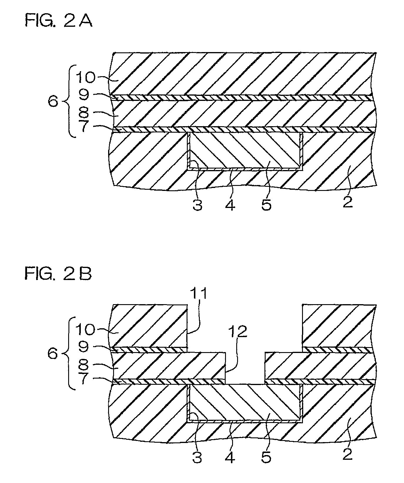
[0046]FIGS. 2A to 2G are schematic sectional views showing the steps of manufacturing the semiconductor device by a method according to the present invention.

[0047]As shown in FIG. 2A, the diffusion preventing film 7, the first interlayer dielectric film 8, the etching stopper film 9 and the second interlayer dielectric film 10 are stacked in this order by CVD (Chemical Vapor Deposition) on the first insulating layer 2 having the first barrier film 4 and the first wire 5 embedded therein. Thus, the second insulating layer 6 is formed on the first insulating layer 2.

[0048]Thereafter the second groove 11 and the via hole 12 are formed in the second insulating layer 6, as shown in FIG. 2B. More specifically, a mask (not shown) having an opening selectively exposing a portion to be provided with the via hole 12 is first formed on the second insulating layer 6. Then, the second interlayer dielectric film 10, the etching stopper film 9 and the first interlayer dielectric film 8 are dry-et...

second embodiment

[0057]FIGS. 3A to 3F are schematic sectional views showing the steps of manufacturing the semiconductor device by a method according to the present invention.

[0058]As shown in FIG. 3A, the diffusion preventing film 7, the first interlayer dielectric film 8, the etching stopper film 9 and the second interlayer dielectric film 10 are stacked in this order by CVD on the first insulating layer 2 having the first barrier film 4 and the first wire 5 embedded therein. Thus, the second insulating layer 6 is formed on the first insulating layer 2.

[0059]Thereafter the second groove 11 and the via hole 12 are formed in the second insulating layer 6, as shown in FIG. 3B. More specifically, a mask (not shown) having an opening selectively exposing a portion to be provided with the via hole 12 is first formed on the second insulating layer 6. Then, the second interlayer dielectric film 10, the etching stopper film 9 and the first interlayer dielectric film 8 are dry-etched through the mask. At th...

third embodiment

[0074]FIGS. 6A to 6E are schematic sectional views showing the steps of manufacturing the semiconductor device by a method according to the present invention. FIG. 7 is a graph showing the relation between an RF bias and coverage of the second groove and the via hole with the alloy film.

[0075]As shown in FIG. 6A, the diffusion preventing film 7, the first interlayer dielectric film 8, the etching stopper film 9 and the second interlayer dielectric film 10 are stacked in this order by CVD on the first insulating layer 2 having the first barrier film 4 and the first wire 5 embedded therein. Thus, the second insulating layer 6 is formed on the first insulating layer 2.

[0076]Thereafter the second groove 11 and the via hole 12 are formed in the second insulating layer 6, as shown in FIG. 6B. More specifically, a mask (not shown) having an opening selectively exposing a portion to be provided with the via hole 12 is first formed on the second insulating layer 6. Then, the second interlaye...


PUM

PropertyMeasurementUnit
thicknessaaaaaaaaaa
thicknessaaaaaaaaaa
thicknessaaaaaaaaaa

Abstract

The method of manufacturing a semiconductor device according to the present invention includes: a groove forming step of forming a groove in an insulating layer made of an insulating material containing Si and O; an alloy film applying step of covering the side surface and the bottom surface of the groove with an alloy film made of an alloy material containing Cu and Mn by sputtering; a thinning step of reducing the thickness of a portion of the alloy film covering the bottom surface of the groove; a wire forming step of forming a Cu wire made of a metallic material mainly composed of Cu in the groove after the thinning step; and a barrier film forming step of forming a barrier film made of MnSiO between the Cu wire and the insulating layer by heat treatment.

Description

BACKGROUND OF THE INVENTION[0001]1. Field of the Invention[0002]The present invention relates to a method of manufacturing a semiconductor device having a Cu wire made of a metallic material mainly composed of Cu (copper).[0003]2. Description of Related Art[0004]In a highly integrated semiconductor device, Cu having higher conductivity than Al (aluminum) may be employed as the material for a wire. A wire made of Cu is embedded in a fine groove formed in an insulating film (an interlayer dielectric film) on a semiconductor substrate by a damascene process, since it is difficult to finely pattern Cu by dry etching.[0005]In general, SiO2 is employed as the material for the insulating film. However, Cu has high diffusibility into SiO2. When the inner surface of the groove formed in the insulating film made of SiO2 and the wire made of Cu are directly in contact with each other, Cu diffuses into the insulating film. This diffusion tends to reduce the dielectric voltage of the insulating ...

Claims


Application Information

Patent Timeline
Patent Type & Authority Patents(United States)
IPC IPC(8): H01L21/68
CPCH01L21/2855H01L21/32051H01L21/76831H01L21/76843H01L21/76844H01L21/76846H01L21/76864H01L21/76865H01L21/76867H01L21/76873H01L23/53238H01L23/5329H01L23/53295H01L2924/0002H01L2221/1089H01L2924/00
Inventor NAKAO, YUICHIKAGEYAMA, SATOSHITAKADA, YOSHIHISA
Owner ROHM CO LTD
Learn More