
Electrostatic transducer, ultrasonic speaker, driving circuit of capacitive load, method of setting circuit constant, display device, and directional sound system

a capacitive load and transducer technology, applied in the field of electrostatic transducers, can solve the problems of large loss wq in the transistor, poor reproduction sound quality, and very narrow frequency band of the transducer, and achieve the effect of sufficient sound pressure, low loss, and flat output frequency characteristi

Inactive Publication Date: 2011-10-18
SEIKO EPSON CORP
View PDF15 Cites 8 Cited by
  • Summary
  • Abstract
  • Description
  • Claims
  • Application Information

AI Technical Summary

Benefits of technology

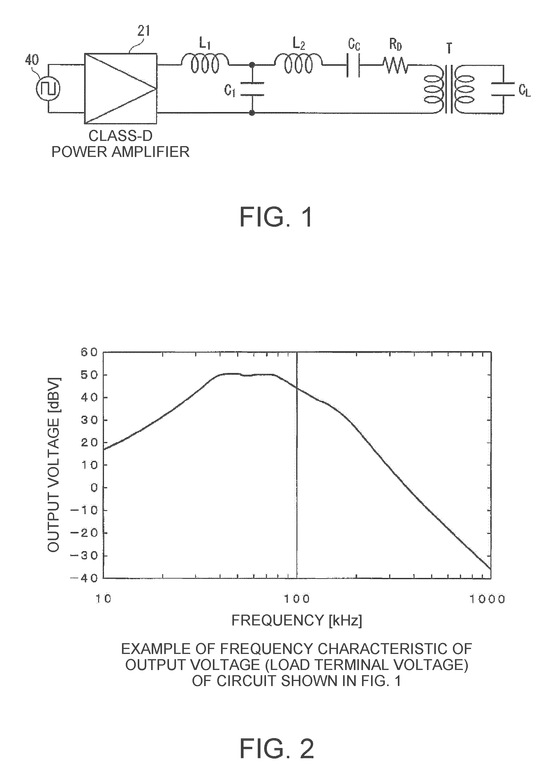
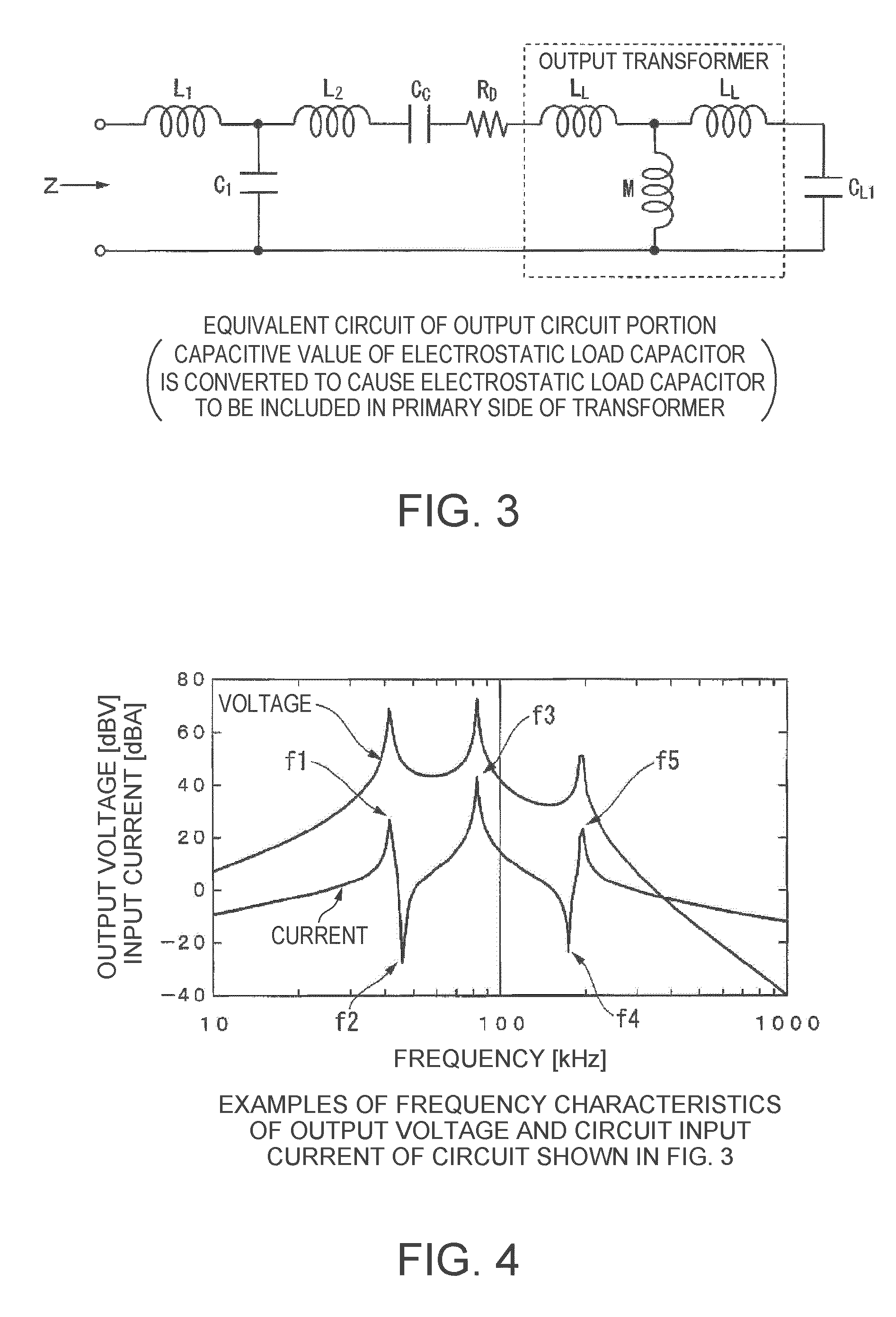
The invention is about an electrostatic transducer that can reduce loss and have a flat frequency characteristic in the driving frequency band. It includes a class-D power amplifier and a low pass filter with a plurality of pairs of inductors and capacitors. The load capacitor of the electrostatic transducer acts as a driving load, and a damping resistor is connected in series with the output transformer. The electrostatic transducer has a driving circuit that includes the low pass filter, the coupling capacitor, the output transformer, and the load capacitor, which has a characteristic of a BPF (band pass filter) and can reduce the loss in the damping resistor. The electrostatic transducer can be used with different types of capacitive loads and can block frequency components in the driving frequency band. The output circuit has a series resonance frequency that matches or approximately matches the carrier wave frequency or rated driving frequency of the electrostatic transducer. The circuit constant is set such that the second series resonance frequency matches or approximately matches the cutoff frequency in the driving frequency band of the electrostatic transducer. This helps to reduce output noises and to block frequency components in the driving frequency band. The electrostatic transducer can be used in an ultrasonic speaker and a display device with a directional sound system.

Problems solved by technology

However, since the piezoelectric transducer uses a sharp resonance characteristic of an element, a frequency band thereof is very narrow even though high sound pressure can be obtained.
As a result, in an ultrasonic speaker using the piezoelectric transducer, a reproducible frequency band is narrow, and accordingly, the reproduced sound quality tends to be poor as compared with a loudspeaker.
However, in the case of driving the electrostatic transducer in an analog amplifier, the following problems occur.
At this time, when the output current IC is a maximum, the voltage VCE is not a minimum but is high, and thus a large loss WQ occurs in the transistor.
As a result, a power loss larger than in the case of the resistive load occurs in the transistor.
Consequently, in the case when the electrostatic transducer is driven by the analog power amplifier, a power amplifier having an output higher than in the case of driving the resistive load is required, which causes a problem in that an apparatus becomes large.
Since the loss in the output-stage element is small in the class-D power amplifier as compared with an analog amplifier, a radiator indispensable to the analog power amplifier may not be prepared or may be made small.
As a result, an unnecessary loss occurs, and thus the circuit efficiency ranging from an amplifier to a load is lowered.
As a result, a serious problem occurs in that the efficiency of the entire driving circuit is noticeably lowered.
In an example shown in FIG. 17, since a characteristic around a driving frequency band of an ultrasonic speaker varies largely, it is not possible to stably drive the ultrasonic speaker with the characteristic described above.
In the example shown in FIG. 17, since the characteristic around the driving frequency band of the ultrasonic speaker varies largely, a problem has occurred in that it is not possible to stably drive the ultrasonic speaker with the characteristic described above.

Method used


Image

  • Electrostatic transducer, ultrasonic speaker, driving circuit of capacitive load, method of setting circuit constant, display device, and directional sound system
  • Electrostatic transducer, ultrasonic speaker, driving circuit of capacitive load, method of setting circuit constant, display device, and directional sound system
  • Electrostatic transducer, ultrasonic speaker, driving circuit of capacitive load, method of setting circuit constant, display device, and directional sound system

Examples


Embodiment Construction

Explanation on a Driving Circuit of an Electrostatic Transducer According to an Embodiment of the Invention

[0110]First, a driving circuit of an electrostatic transducer using a class-D power amplifier according to an embodiment of the invention will be described.

[0111]The driving circuit of the electrostatic transducer according to the embodiment of the invention has a characteristic of a BPF, in terms of the entire circuit, by applying a load capacitor as one of constituent components of a low pass filter and inserting a coupling capacitor, a damping resistor, and an output transformer in the low pass filter in the driving circuit of the electrostatic transducer driven by a class-D power amplifier. This makes it possible to realize a flat output voltage frequency characteristic and to reduce a circuit loss in a driving frequency band of a transducer. Accordingly, it is possible to reduce both a loss in a load resistor and a loss in an output-stage element of a power amplifier, such...


PUM


Abstract

An electrostatic transducer includes: a class-D power amplifier that amplifies an input signal; and a low pass filter that has a plurality of pairs of inductors and capacitors, is connected to an output side of the class-D power amplifier, and serves to eliminate switching carrier components included in an output of the class-D power amplifier. An electrostatic load capacitor of the electrostatic transducer serving as a driving load is disposed at a capacitor, which is closest to the output side of the class-D power amplifier, of circuit elements forming the low pass filter, an electrostatic coupling capacitor and an output transformer are interposed between the electrostatic load capacitor of the electrostatic transducer and an inductor closest to the output side of the class-D power amplifier of the low pass filter, and a damping resistor is connected in series to a primary coil of the output transformer.

Description

BACKGROUND[0001]1. Technical Field[0002]The present invention relates to an electrostatic transducer. In particular, the invention relates to an electrostatic transducer having a driving circuit, which is suitable for an electrostatic transducer that reproduces a sound having high directionality by outputting a modulated wave obtained by modulating a carrier wave in an ultrasonic band with a sound signal in an audible band, to a method of setting a circuit constant of the electrostatic transducer, to an ultrasonic speaker, to a display device having the ultrasonic speaker, to a directional sound system, and to a driving circuit of a capacitive load.[0003]2. Related Art[0004]An ultrasonic speaker can reproduce a sound having high directionality by outputting a modulated wave obtained by modulating a carrier wave in an ultrasonic band with a sound signal in an audible band. In general, a piezoelectric transducer is used as a transducer (transmitter) of the ultrasonic speaker. However,...

Claims


Application Information

Patent Timeline
Patent Type & Authority Patents(United States)
IPC IPC(8): H04R25/00H04R3/00
CPCH04R3/06H04R19/02H04R5/02H04R2217/03H04R2499/15
Inventor MIYAZAKI, SHINICHI
Owner SEIKO EPSON CORP
Learn More