Magneto-inductive flow measuring device

Inactive Publication Date: 2011-10-25
ENDRESS HAUSER FLOWTEC AG
View PDF21 Cites 4 Cited by
  • Summary
  • Abstract
  • Description
  • Claims
  • Application Information

AI Technical Summary

Benefits of technology

[0009]In the case of known, magnetically inductive, flow measuring devices with usual measuring electrodes, the polarity of the magnetic field periodically changes. By forming the difference between two, succeeding, measured values ascertained at different polarities of the magnetic field, signal portions representing the disturbance variables and, thus, not reflecting the volume- or mass-flow to be ascertained, can be effective

Problems solved by technology

It is clear, that an electrochemical potential changing as a function of time influences negatively the accuracy of measurement of a conventional, magnetically inductive, flow measuring device.
Due to the influence of the

Method used


Image

  • Magneto-inductive flow measuring device
  • Magneto-inductive flow measuring device
  • Magneto-inductive flow measuring device

Examples


Example

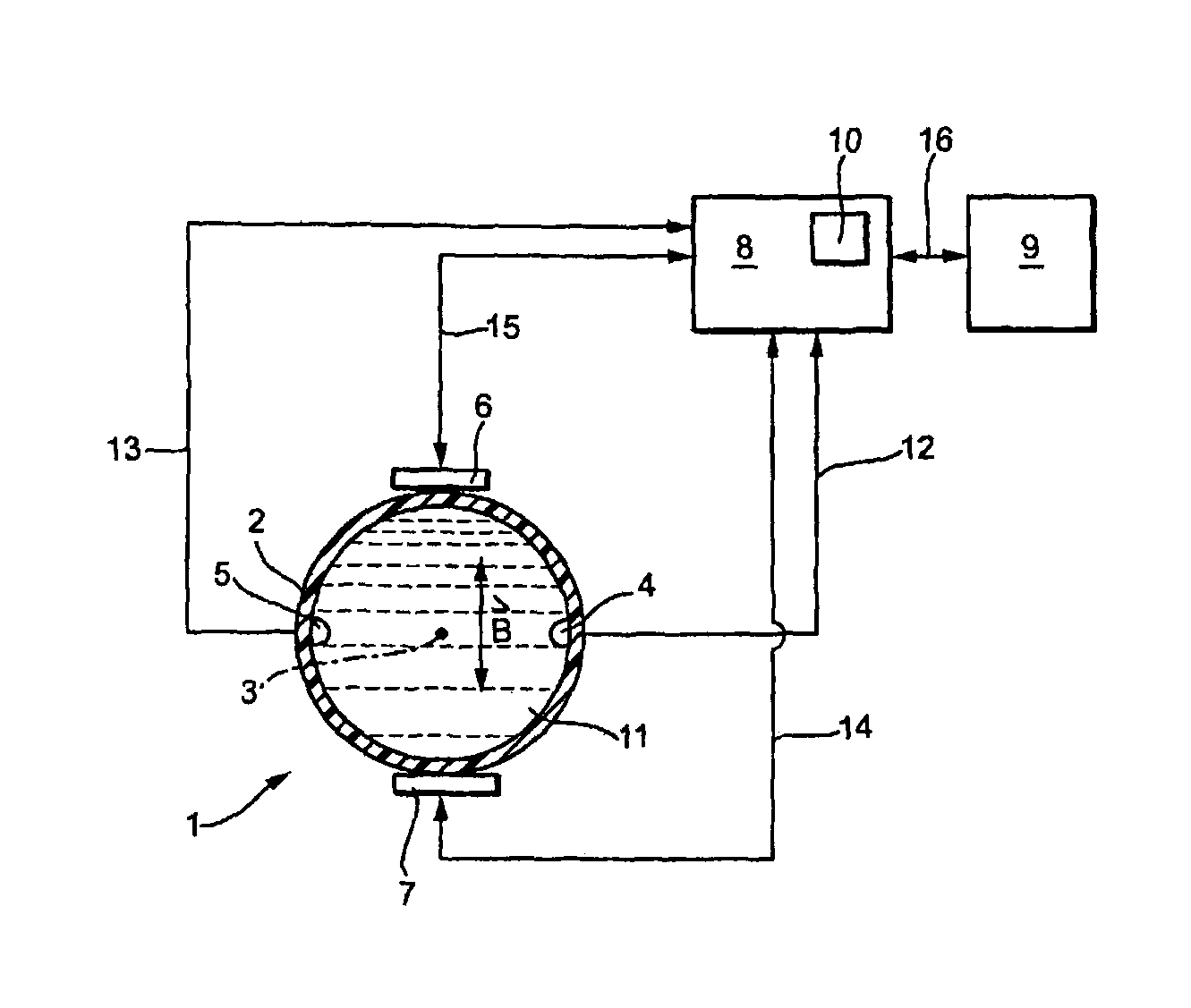
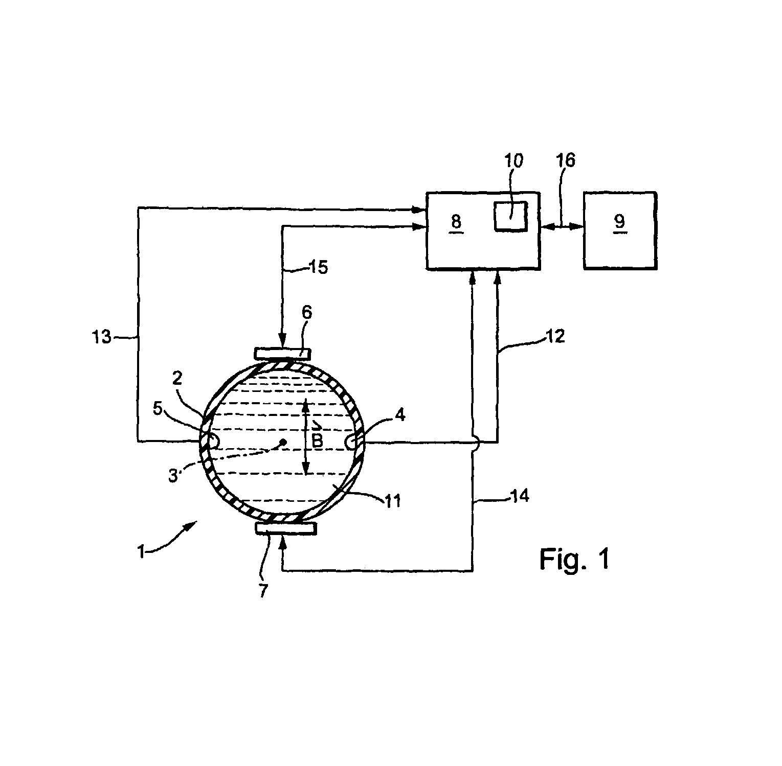
[0015]FIG. 1 shows a schematic drawing of a first embodiment of the apparatus of the invention. Medium 11 flows through the measuring tube 2 in the direction of the measuring tube axis 3. The medium 11 is at least slightly electrically conductive. The measuring tube 2 itself is made of a non-conductive material, or, at least its inner surface is lined with a non-conductive material.

[0016]The magnetic field B directed perpendicularly to the flow direction of the medium 11 is produced via the two, diametrally arranged, electromagnets 6, 7. The magnetic field B is either a constant magnetic field or an alternating magnetic field periodically reversing its direction. Under the influence of the magnetic field B, charge carriers located in the medium 11 migrate, according to their polarity, to one of the two oppositely poled, measuring electrodes 4, 5. The voltage established between the measuring electrodes 4, 5 is proportional to the flow velocity of the medium 11 averaged over the cros...


PUM


Abstract

An apparatus for measuring volume- or mass-flow of a medium flowing through a measuring tube in the direction of the measuring tube axis, and includes: a magnet system, which produces a magnetic field passing through the measuring tube essentially transversely to the measuring tube axis; at least one measuring electrode, which contacts the medium in a defined surface region; and a control/evaluation unit, which provides information concerning volume- or mass flow of the medium in the measuring tube on the basis of a measurement voltage induced in the at least one measuring electrode. At least the medium-contacting surface region of the at least one measuring electrode is manufactured of a chemically inert and electrochemically and mechanically resistant material.

Description

TECHNICAL FIELD[0001]The invention relates to a magnetically inductive flow measuring device, thus, an apparatus for measurement of volume- or mass-flow, e.g. flow rate, of a medium flowing through a measuring tube in the direction of the measuring tube axis. The apparatus includes: A magnet system, which produces a magnetic field passing through the measuring tube essentially transversely to the measuring tube axis; at least one measuring electrode, which is in contact with the medium in a defined surface region; and a control / evaluation unit, which provides information concerning the volume- or mass-flow of the medium in the measuring tube on the basis of a measurement voltage induced in the at least one measuring electrode.BACKGROUND DISCUSSION[0002]Magneto-inductive flow measuring devices utilize the principle of electrodynamic induction for volumetric flow measurement: charge carriers of the medium moved perpendicularly to a magnetic field induce a measurement voltage in measur...

Claims


Application Information

Patent Timeline
IPC IPC(8): G01F1/58
CPCG01F1/584G01F1/60
Inventor BUDMIGER, THOMASSZALOKY, GEORG
Owner ENDRESS HAUSER FLOWTEC AG
Why Eureka
Try Eureka