Adjusting valve timing to deactivate engine cylinders for variable displacement operation

a variable displacement, valve timing technology, applied in the direction of machines/engines, output power, couplings, etc., can solve the problems of not eliminating the valve deactivator, not being able to adjust both intake and exhaust valve events, and overlap of valves, so as to facilitate a smooth transition of torque

Active Publication Date: 2011-10-25
FORD GLOBAL TECH LLC
View PDF22 Cites 22 Cited by
  • Summary
  • Abstract
  • Description
  • Claims
  • Application Information

AI Technical Summary

Benefits of technology

[0009]Valve deactivation according to the present disclosure presents an advantage by using exhaust cam phasing to effectively disable the cylinder as opposed to the solution shown in U.S. Pat. No. 6,237,599 in which exhaust valve deactivators are employed. As typical of hydraulic variable cam timing devices, the VCT device in '599 has insufficient range of authority to adjust exhaust valve timing to provide substantially no valve overlap and relies on valve deactivators on the exhaust valves. The valve deactivation strategy of the present disclosure also presents an advantage over strategies such as shown in U.S. Pat. No. 5,642,703 because adjusting the exhaust and intake valve events independently allows operation with substantially no valve overlap. Thus, unintended exhaust flow into the intake is substantially eliminated.
[0010]Use of a mechanical cam phasing device, such as disclosed herein, provides a greater range of authority, thereby facilitating adjusting the exhaust camshaft to a position in which there is substantially no net flow of gases through the exhaust valves. Such camshaft phasing device acts upon each camshaft as a whole. Thus, in an engine having two cylinder banks, one bank of cylinders may be operated with conventional valve timings, whereas, the valve timings of the other bank of cylinders are adjusted to deactivate the cylinders.
[0012]Furthermore, most valve deactivation systems deactivate (or activate) valves in an abrupt manner causing one-half of engine cylinders to turn off (or turn on) abruptly. It is difficult to manage engine torque to obtain a smooth transition under such conditions. Yet another advantage of an embodiment of the present disclosure is that the valve adjustments to the symmetric valve timing can be accomplished over a number of engine cycles to facilitate a smooth transition in torque.

Problems solved by technology

However, such a system does not eliminate valve deactivators, which are known to be problematic.
For example, there are typically issues associated with latching the valve deactivators and difficulties in ensuring that they are latched within one engine cycle, particularly at high engine speeds.
Thus, it is not possible to adjust both intake and exhaust valve events such that they are symmetrical about a rotational position of the crankshaft when the direction of the piston changes, i.e., TC or BC.
Also, valve overlap, which lasts about 25 degrees of crank rotation is not adjusted in such a system because the intake and exhaust valve events move in lock step.
For example, when operating at low torque conditions, there is a considerable intake manifold vacuum to drive flow from the exhaust to the intake.
However, this is an operating condition where no additional exhaust gases can be accommodated without impairing combustion stability.
As typical of hydraulic variable cam timing devices, the VCT device in '599 has insufficient range of authority to adjust exhaust valve timing to provide substantially no valve overlap and relies on valve deactivators on the exhaust valves.
When such cylinders are reactivated, the excess oil is burned, which is generally undesirable.
Furthermore, most valve deactivation systems deactivate (or activate) valves in an abrupt manner causing one-half of engine cylinders to turn off (or turn on) abruptly.
It is difficult to manage engine torque to obtain a smooth transition under such conditions.

Method used


Image

  • Adjusting valve timing to deactivate engine cylinders for variable displacement operation
  • Adjusting valve timing to deactivate engine cylinders for variable displacement operation
  • Adjusting valve timing to deactivate engine cylinders for variable displacement operation

Examples


Embodiment Construction

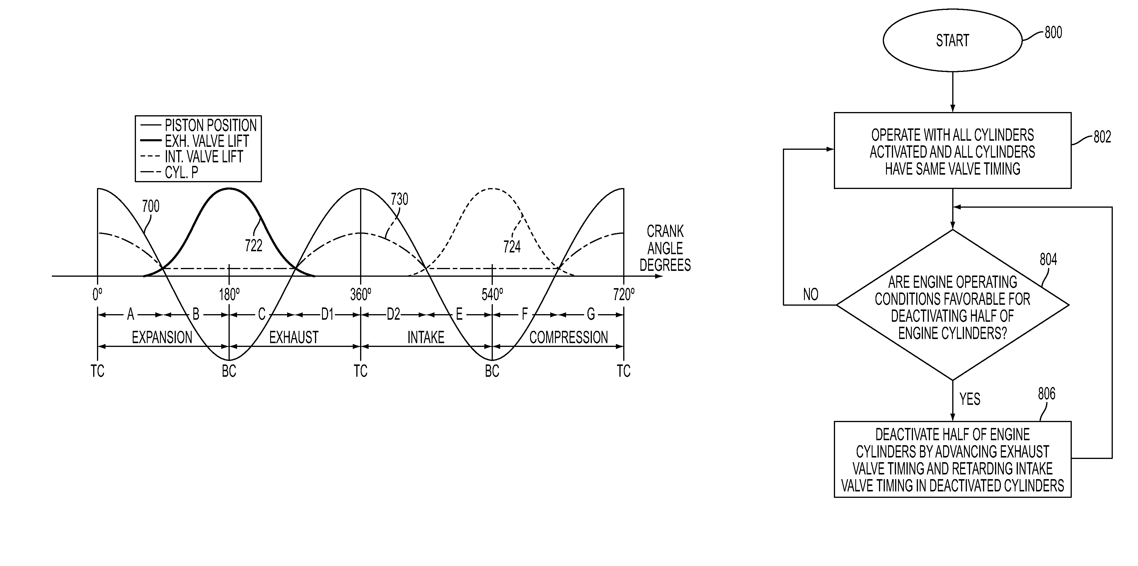
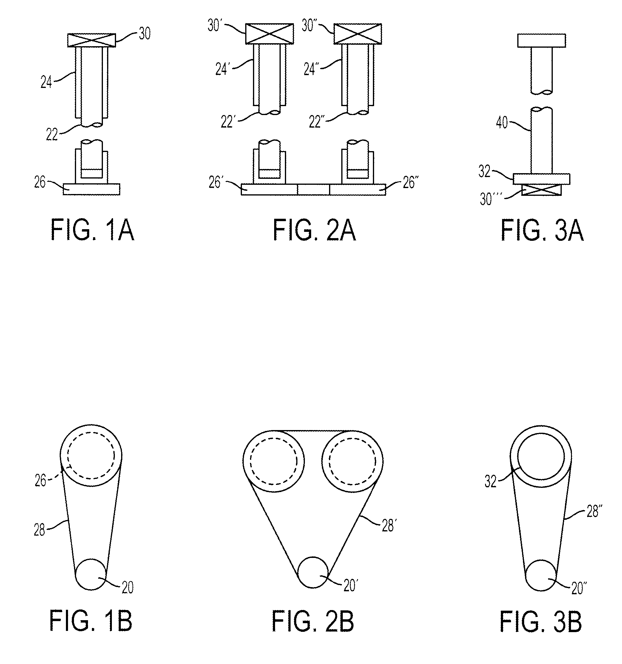
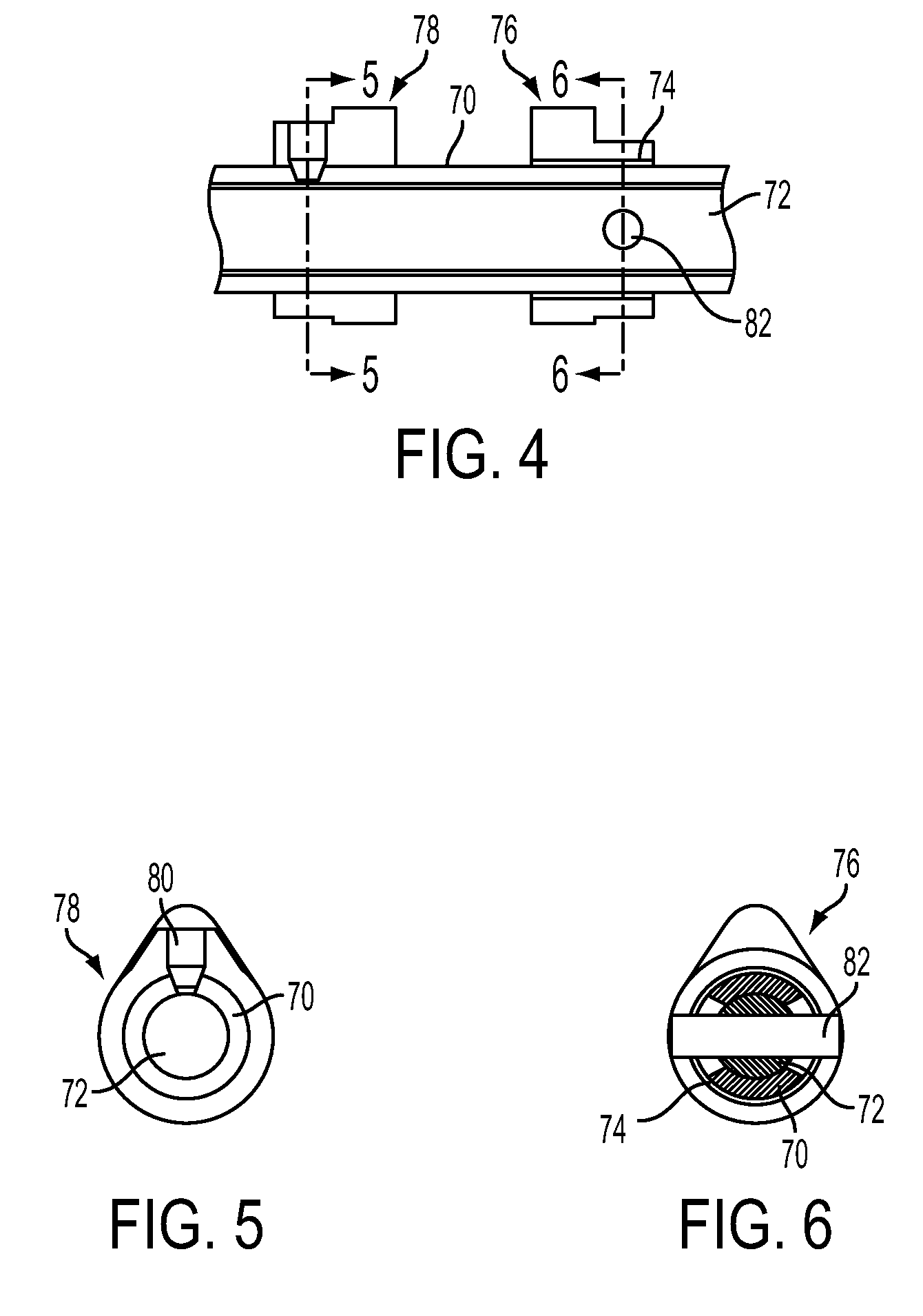
[0039]As those of ordinary skill in the art will understand, various features of the embodiments illustrated and described with reference to any one of the Figures may be combined with features illustrated in one or more other Figures to produce embodiments that are not explicitly illustrated or described. The combinations of features illustrated provide representative embodiments for typical applications. However, various combinations and modifications of the features consistent with the teachings of the present disclosure may be desired for particular applications or implementations. The representative embodiments used in the illustrations relate generally to a multi-cylinder, internal combustion engine having a non-hydraulic variable cam timing device to vary the angular relationship between the camshaft and crankshaft and / or between sets of camshaft lobes to provide variable displacement operation by selectively deactivating cylinders by adjusting valve timing. However, those of...


PUM


Abstract

An internal combustion engine having two cylinder banks and adjustable camshaft timing is disclosed in which the camshafts in one cylinder bank are adjusted so that there is no net flow from the cylinders to effectively disable the cylinder bank. In particular, exhaust valve timing is advanced so that the maximum valve lift occurs approximately at bottom center between expansion and exhaust strokes and intake valve timing is advanced so that maximum valve lift occurs approximately at bottom center between intake and compression strokes. Also disclosed is an engine in which an intake and an exhaust camshaft on a single bank are coaxial with valve timings adjusted by rotating the inner of the two camshafts with respect to the outer of the two camshafts.

Description

CROSS-REFERENCE TO RELATED APPLICATION[0001]This application is a continuation-in-part of commonly owned and copending U.S. application Ser. No. 12 / 351,049, which is hereby incorporated by reference in its entirety.BACKGROUND[0002]1. Technical Field[0003]The present disclosure relates to using a variable camshaft timing device to deactivate a portion of engine cylinders.[0004]2. Background Art[0005]Variable camshaft timing (VCT) devices are used to change the phase relationship between the crankshaft and the camshaft lobes that control actuation of the intake and exhaust poppet valves. By controlling the phase relationship, the fuel economy, performance, and emissions can be improved by providing less valve overlap at low engine speed operation to improve combustion stability, and more valve overlap at higher engine speed to improve engine power and performance.[0006]It is known that by deactivating a portion of engine cylinders when the engine is operating at light load, that overa...

Claims


Application Information

Patent Timeline
Patent Type & Authority Patents(United States)
IPC IPC(8): F01L1/34
CPCF01L1/34406F02D13/06F01L2001/0473Y02T10/18Y02T10/12
Inventor BERGER, ALVIN HENRY
Owner FORD GLOBAL TECH LLC
Why Eureka
Try Eureka