Thermocouple vacuum gauge

a vacuum gauge and thermocouple technology, applied in the direction of thermometers, instruments, material thermal analysis, etc., can solve the problems of affecting the cooling time, the operation method cannot be used within a relatively small pressure measurement range, and the cooling time is not evaluated

Inactive Publication Date: 2011-11-01
HEINZ PLOECHINGER
View PDF13 Cites 223 Cited by
  • Summary
  • Abstract
  • Description
  • Claims
  • Application Information

AI Technical Summary

Benefits of technology

As both thermal conductivity and heat capacity decrease with pressure only a small amount of heating energy is required for the thermocouple to be heated from its lower threshold temperature to its upper threshold temperature at the lower end of the measuring range. To increase the sensor's sensitivity at low pressure the power applied to the thermocouple may be reduced. The reduced power increases the heating time, thereby improving the sensor's resolution and extending its measurement range at low pressure.
In contrast to operating methods which maintain a constant high temperature of the thermocouple, the variable temperature operating method according to one aspect of the invention operates at high temperature only during short periods of time at the end of a measuring cycle. The average temperature of and average power applied to the thermocouple utilizing a variable temperature operating method may be significantly lower than those of a thermocouple operating at constant temperature. This is advantageous especially when measuring pressure of small gas volumes, for example in analytical instruments, to limit the power applied to the gas and thereby the influence that measuring its pressure has on the gas in the probe.

Problems solved by technology

Unfortunately this operating method can only be used within a relatively small pressure measurement range.
A disadvantage is that the low voltage applied during cooling influences the cooling time.
However, the described vacuum gauges only evaluate the time required to reach a specified temperature during heating.
The cooling time is not evaluated, since measuring the resistance of the Pirani element requires applying a measuring voltage, which interferes with the cooling of the element.

Method used


Image

  • Thermocouple vacuum gauge
  • Thermocouple vacuum gauge
  • Thermocouple vacuum gauge

Examples


Embodiment Construction

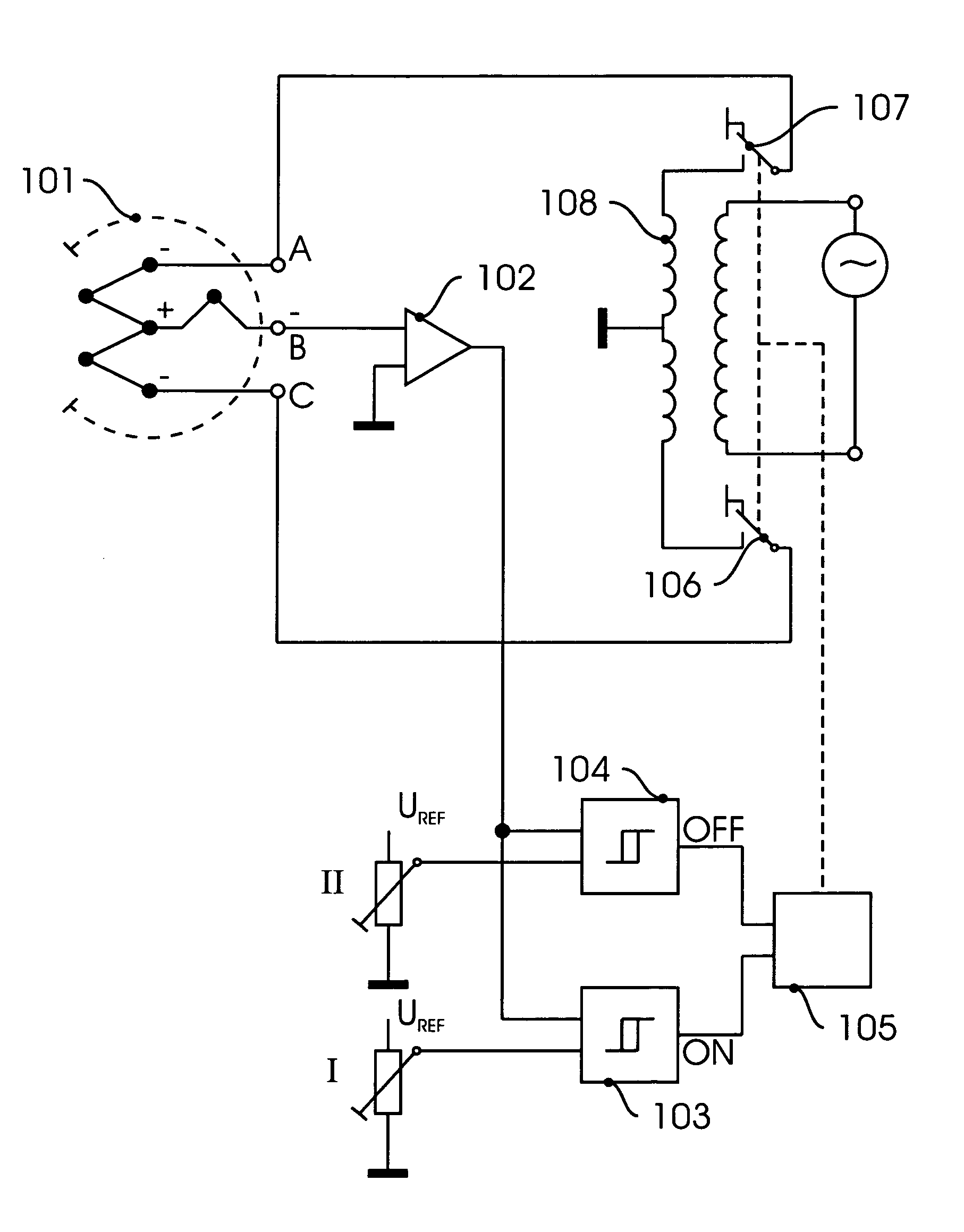
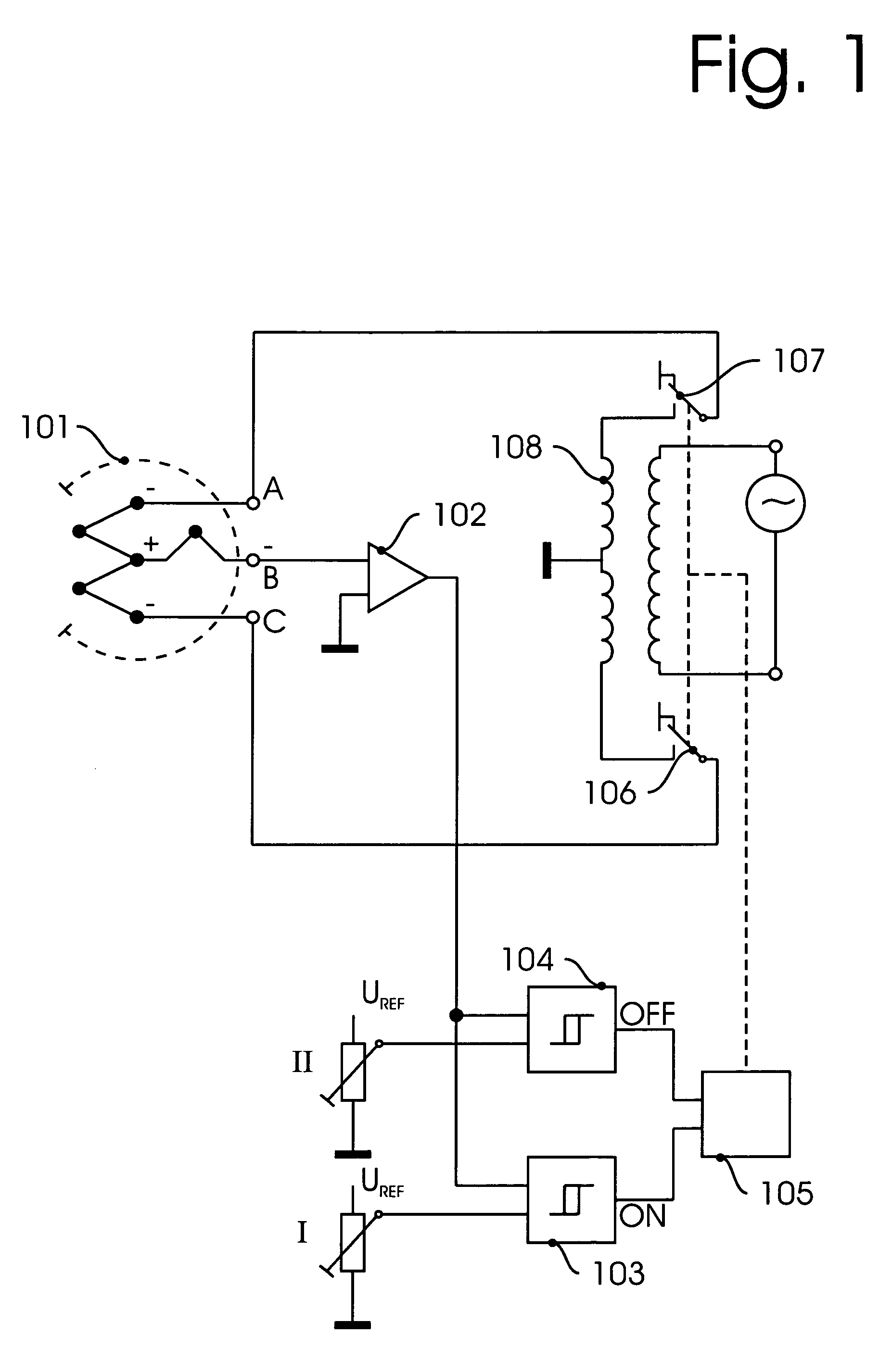
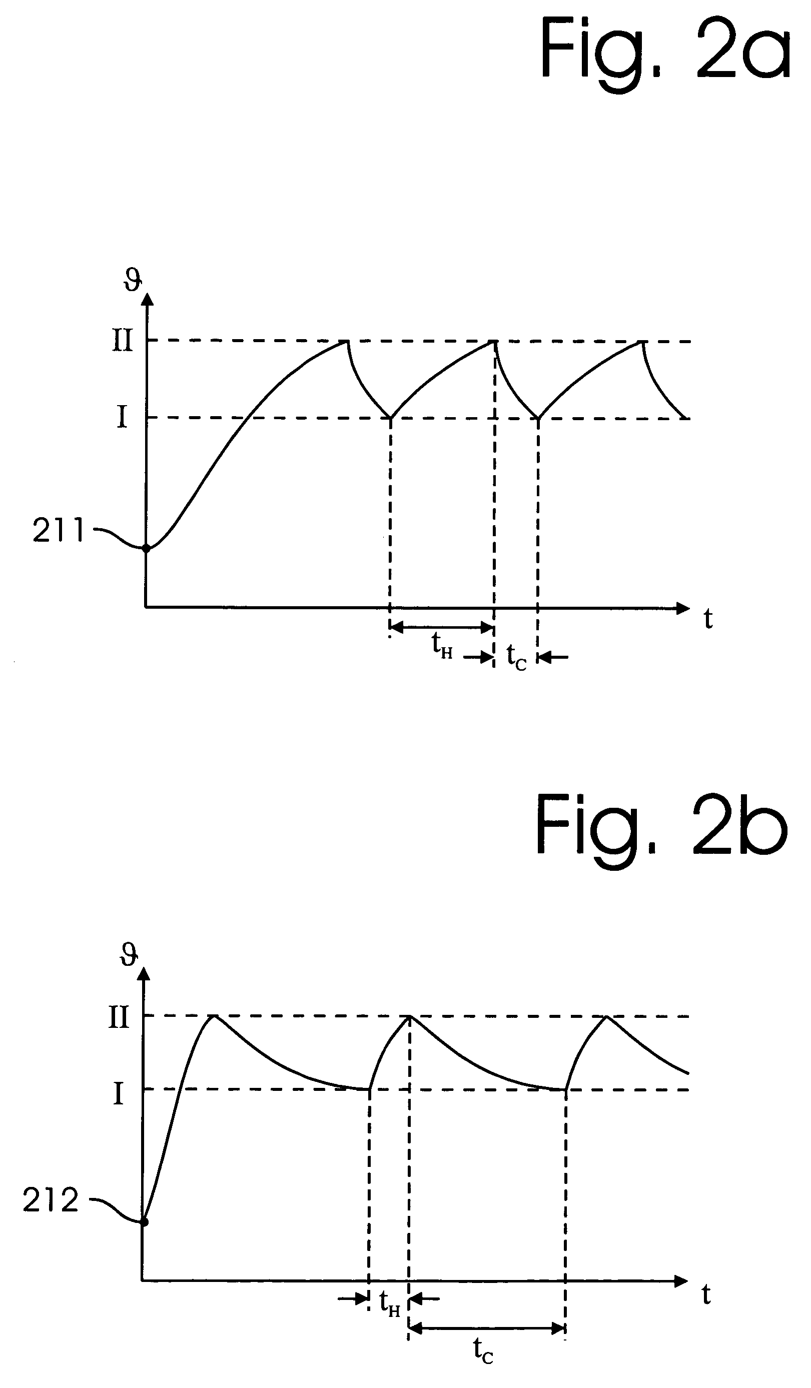
Referring to FIG. 1, a block diagram of an exemplary system in which the principles of the present invention may be advantageously practiced is illustrated generally. A thermocouple sensor 101, e.g. a commercially available vacuum measuring tube model DV-4 or DV-6 manufactured by Teledyne Hastings, is operatively connected to an operating circuit through connections A, B, and C. A variable temperature operating method is used wherein the temperature at the thermocouples continuously cycles between a lower threshold θI and an upper threshold θII. This is achieved by modifying a traditional constant temperature sensor system such that an alternating heating voltage which is applied to a series connection of two thermocouples can be selectively turned on and off through switches 106 and 107.

In the exemplary circuit thermoelectric voltage output B is operatively connected to an amplifier 102. The output of amplifier 102 is connected in parallel to a first comparator 103 having switching...


PUM

PropertyMeasurementUnit
pressureaaaaaaaaaa
thermoelectric voltageaaaaaaaaaa
timeaaaaaaaaaa

Abstract

A thermocouple vacuum sensor is provided, the thermocouple being surrounded by a gas or mixture of gases the pressure of which is to be measured. Cyclically the thermocouple is heated until its temperature reaches an upper temperature threshold. The thermocouple is subsequently cooled until its temperature reaches a lower temperature threshold. The heating time required to heat the thermocouple from the lower to the upper temperature threshold is measured. The cooling time required to cool the thermocouple from the upper temperature threshold to the lower temperature threshold may also be measured. The pressure surrounding the thermocouple may then be determined as a function of either the heating time, or the cooling time, or both.

Description

TECHNICAL FIELDThe present invention generally relates to a thermocouple apparatus to measure pressures in a partial vacuum, and more particularly, to a thermocouple apparatus using a time-measurement operating method to measure pressure over a wide range.BACKGROUND OF THE INVENTIONThermocouple measuring tubes are known in the art to measure pressure in a partial vacuum. A change in pressure in the measuring tube changes the molecular collision rate and therefore the thermal conduction of the gas or gas mixture surrounding the thermocouple. Such measuring tubes are typically operated using one of two alternative operating methods.In a first operating method, an alternating voltage is continuously applied to the thermocouple, thereby heating the thermocouple. The resulting temperature shift depends on the pressure of the surrounding gas or gas mixture and causes a change in the thermocouple's DC output inversely with pressure changes. Unfortunately this operating method can only be u...

Claims


Application Information

Patent Timeline
Patent Type & Authority Patents(United States)
IPC IPC(8): G01L21/14
CPCG01L21/14
Inventor PLOECHINGER, HEINZ
Owner HEINZ PLOECHINGER
Why Eureka
Try Eureka