Clean corona gas ionization for static charge neutralization

a gas ionization and static charge technology, applied in the direction of variable capacitors, magnetic separation, vapor flow control, etc., can solve the problem of not being strong enough to move substantially any contaminant byproducts into the non-ionized gas stream, and achieve efficient ion harvesting and transfer, reduce particle generation and corona chemical reactions, and reduce charge accumulation

Active Publication Date: 2011-11-01
ILLINOIS TOOL WORKS INC
View PDF50 Cites 31 Cited by
  • Summary
  • Abstract
  • Description
  • Claims
  • Application Information

AI Technical Summary

Benefits of technology

[0020]In one form, the invention comprises a method separating ions and contaminant particles by presenting at least one non-ionized gas stream having a pressure and flowing in a downstream direction while maintaining a lower pressure in the plasma region at the ionizing electrode. For example, this embodiment may use a through-channel that surrounds the ion drift region, while a low-pressure emitter shell, at least partially disposed within the non-ionizing stream, substantially shields the ionizing electrode and its plasma region from the non-ionized gas stream of the ion drift region. The resulting pressure differential prevents at least a substantial portion of the contaminant byproducts from moving out of the plasma region and into the non-ionizing stream.
[0021]Additionally, some forms of the present invention envision gas flow ionizers for creating gas ions with concurrent removal of corona byproducts. The inventive ionizers may have at least one through-channel and a shell assembly. The assembly may include an emitter shell, some means for producing a plasma region comprising ions and contaminant byproducts to which an ionizing electrical potential may be applied. The means for producing ions (such as an emitter) and its associated plasma region may be at least partially disposed within the emitter shell and the shell may have an orifice to allow at least a substantial portion of the ions to migrate into the non-ionized gas stream (the main gas stream) flowing through the ion drift region and within the through-channel. At least a portion of the plasma region may be maintained at a pressure low enough to prevent substantially all of the corona byproducts from migrating into the main ion stream, but not low enough to prevent at least a substantial portion of the gas ions from migrating into the main ion stream. The gas flowing through the ion drift region of the through-channel may, thus, be converted into a clean ionized gas stream that delivers these ions in the downstream direction of the neutralization target. Simultaneously, the low pressure emitter shell may protect or shield the means for producing ions and its plasma region from the relatively high pressure of the non-ionized gas stream such that substantially no contaminant byproducts migrate into the main ion stream.
[0024]Another optional feature of the present invention includes the use of a vacuum and / or a low-pressure sensor with an output that is communicatively linked to an ionizer control system. With such an arrangement the control system may be used to take various actions in response to a trigger signal. For example, the control system may shut down the high voltage power supply to thereby prevent gas flow in the through-channel from being contaminated by corona byproducts if the pressure level in the evacuation port increases above a predetermined threshold level.
[0028]The through-channel may be made, at least in part, from a highly resistive material and the reference electrode may be positioned on the external surface of the through-channel. As a result, efficient ion harvesting and transfer by the high-pressure gas stream may be achieved at lower corona currents because particle generation and corona chemical reactions are reduced.
[0029]In another optional aspect of the invention, AC voltage may be applied to the at least one emitter to create a bipolar plasma region near the emitter tip and at least greatly reduce charge accumulation on corona-generated contaminant particles. As a result, electrical mobility of the contaminant particles is further decreased separation between ions and corona byproducts is enhanced.

Problems solved by technology

The non-ionizing electrical field should be strong enough to induce the ions to enter into the non-ionized gas stream to thereby form an ionized gas stream, but not strong enough to move substantially any contaminant byproducts into the non-ionized gas stream.

Method used


Image

  • Clean corona gas ionization for static charge neutralization
  • Clean corona gas ionization for static charge neutralization
  • Clean corona gas ionization for static charge neutralization

Examples


Embodiment Construction

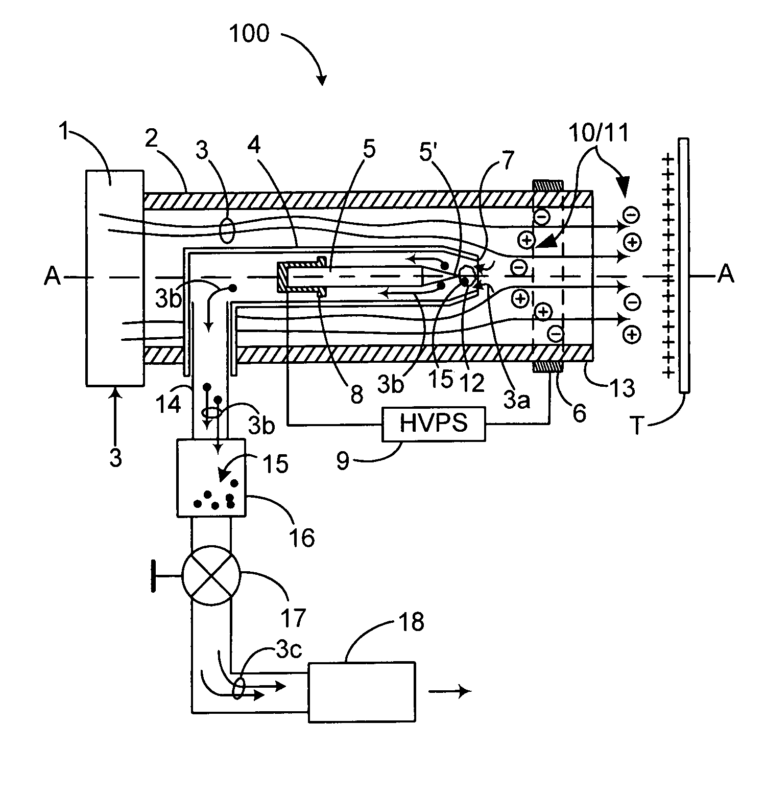
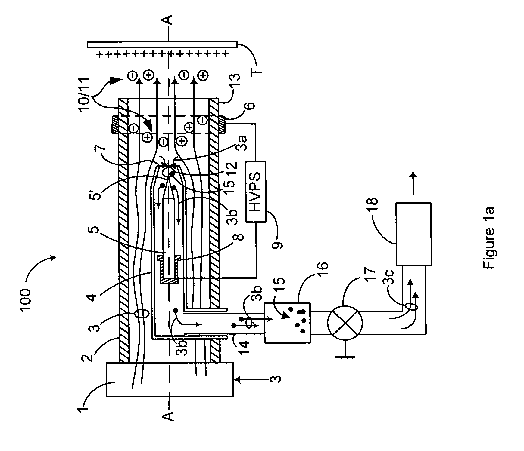
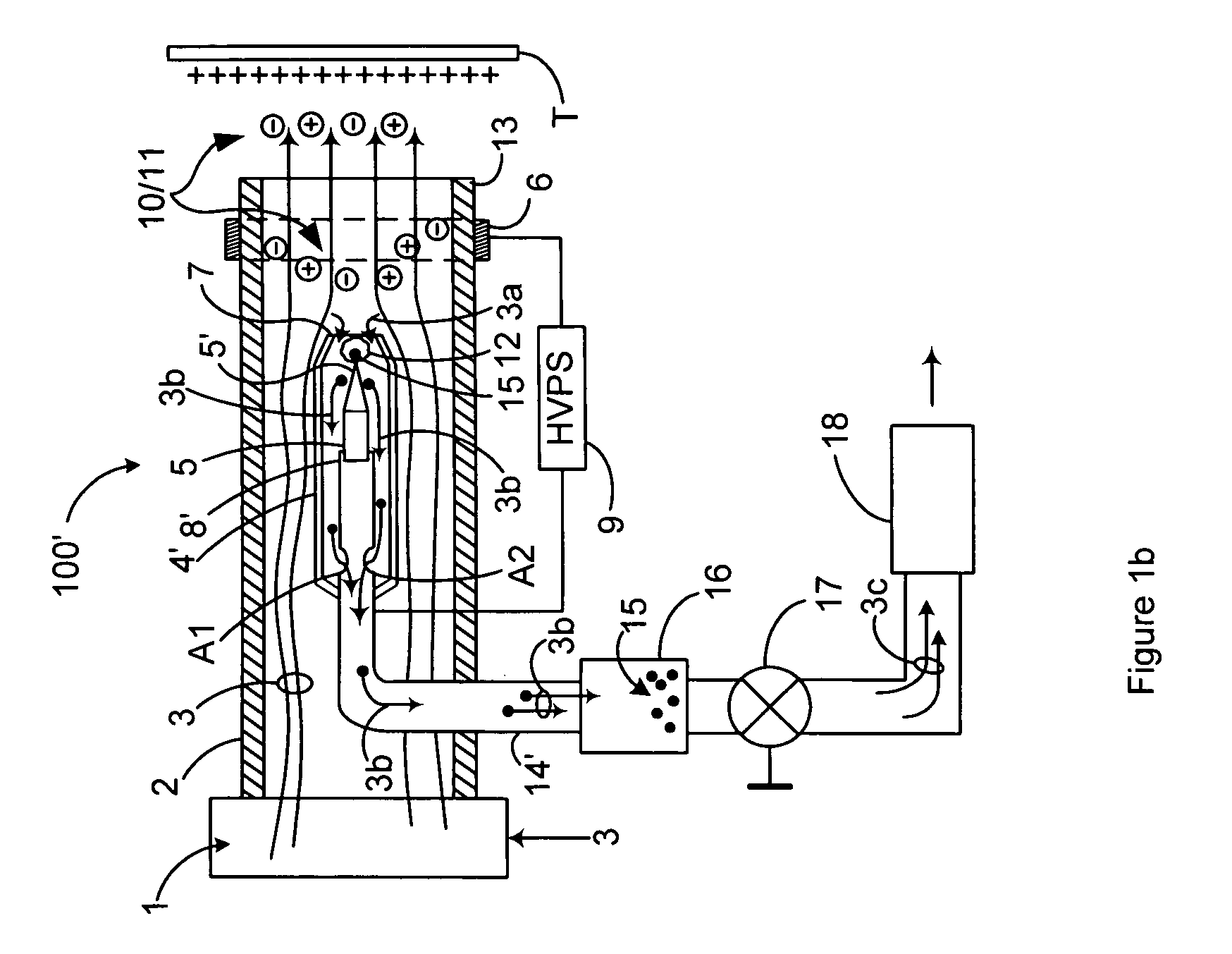
[0046]FIG. 1a is a schematic representation of first preferred method and apparatus embodiments of the invention. Cross-sectional elevation and perspective views of FIGS. 3a and 3b conveying various structural details of the inventions represented by FIG. 1a and reference to these Figures is, therefore, also made.

[0047]As shown in the aforementioned Figures, an inventive in-line ionization cell 100 includes at least one emitter (for example, an ionizing corona electrode) 5 received within a socket 8 and both are located inside a hollow emitter shell 4. The electrode / emitter 5 may be made from a wide number of known metallic and non-metallic materials (depending on the particular application / environment in which it will be used) including single-crystal silicon, polysilicon, etc. The emitter shell 4 is preferably positioned coaxially along axis A-A inside a preferably highly resistive through-channel 2 that defines a passage for gas flow therethrough. As an alternative, through-chann...


PUM


Abstract

Clean corona gas ionization by separating contaminant byproducts from corona generated ions includes establishing a non-ionized gas stream having a pressure and flowing in a downstream direction, establishing a plasma region of ions and contaminant byproducts in which the pressure is sufficiently lower than the pressure of the non-ionized gas stream to prevent at least a substantial portion of the byproducts from migrating into the non-ionized gas stream, and applying an electric field to the plasma region sufficient to induce at least a substantial portion of the ions to migrate into the non-ionized gas stream.

Description

CROSS REFERENCE TO RELATED CASES[0001]This application claims the benefit under 35 U.S.C. 119(e) of the following co-pending U.S. Applications: U.S. application Ser. No. 61 / 214,519 filed Apr. 24, 2009 and entitled “Separating Particles and Gas Ions in Corona Discharge Ionizers”; U.S. application Ser. No. 61 / 276,792 filed Sep. 16, 2009 entitled “Separating Particles and Gas Ions in Corona Discharge Ionizers”; U.S. application Ser. No. 61 / 279,784, filed Oct. 26, 2009 and entitled “Covering Wide Areas With Ionized Gas Streams”; U.S. application Ser. No. 61 / 337,701 filed Feb. 11, 2010 and entitled “Separating Contaminants From Gas Ions In Corona Discharge Ionizers”; which applications are all hereby incorporated by reference in their entirety.BACKGROUND OF THE INVENTION[0002]1. Field of the Invention[0003]The invention relates to the field of static charge neutralization apparatus using corona discharge for gas ion generation. More specifically, the invention is directed to producing co...

Claims


Application Information

Patent Timeline
Patent Type & Authority Patents(United States)
IPC IPC(8): B03C3/36
CPCB03C3/017B03C3/155B03C3/383B03C3/49B03C3/41B03C2201/24B03C2201/06B01J19/08B03C3/38H05F3/04H01J47/02
Inventor GEFTER, PETERKLOCHKOV, ALEKSEYMENEAR, JOHN E.NELSEN, LYLE DWIGHT
Owner ILLINOIS TOOL WORKS INC
Why Eureka
Try Eureka