Contrast rear projection screen and method for manufacturing the same

a rear projection screen and contrast technology, applied in the field of contrast rear projection screen and method for manufacturing the same, can solve the problems of not always achieving optically, illuminating portions of the image with spurious light, and particular loss of contrast, so as to improve the contrast of such screens, reduce the effect of illuminating portions of the image and reducing the loss of contras

Active Publication Date: 2011-11-01
LIGON THOMAS R
View PDF9 Cites 12 Cited by
  • Summary
  • Abstract
  • Description
  • Claims
  • Application Information

AI Technical Summary

Benefits of technology

[0009]As noted above, wrap-around rear projection screens, including those of spherical, hemispherical, and cylindrical geometry, suffer a particular lost of contrast due to back scattering of the projected light falling on opposite portions of the screen and the projected image, thereby illuminating portions of the image with spurious light. The present invention substantially improves the contrast of such screens by using a tinted attenuation layer situated between the diffusion layer and the projection source. This tinted attenuation layer diminishes the back-scattere

Problems solved by technology

As noted above, wrap-around rear projection screens, including those of spherical, hemispherical, and cylindrical geometry, suffer a particular lost of contrast due to back scattering of the projected light falling on opposite portions of the screen and the projected image, thereby illuminating portions of the image with spurious light.
Although there are several ways to position a tinted attenuation layer between the projection source and the diffusion layer so that back-scattered light must travel through the tinted attenuation layer three times before it can impinge on other parts of the rear projection screen, such arrangements do not always result in an optically-even distri

Method used


Image

  • Contrast rear projection screen and method for manufacturing the same
  • Contrast rear projection screen and method for manufacturing the same
  • Contrast rear projection screen and method for manufacturing the same

Examples


Embodiment Construction

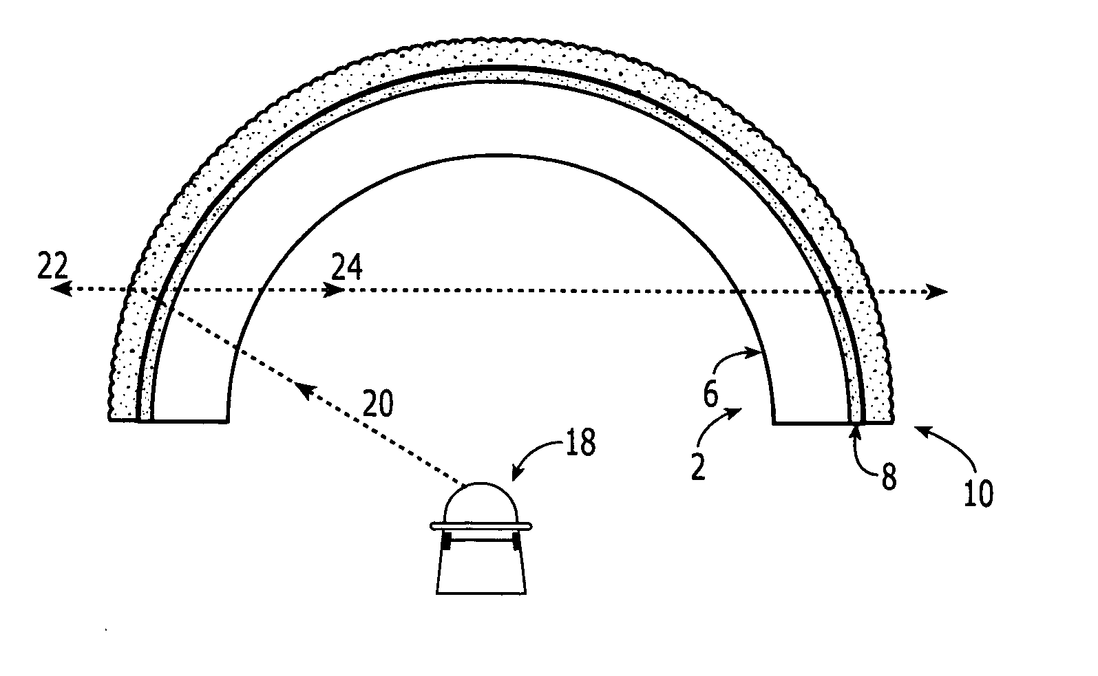
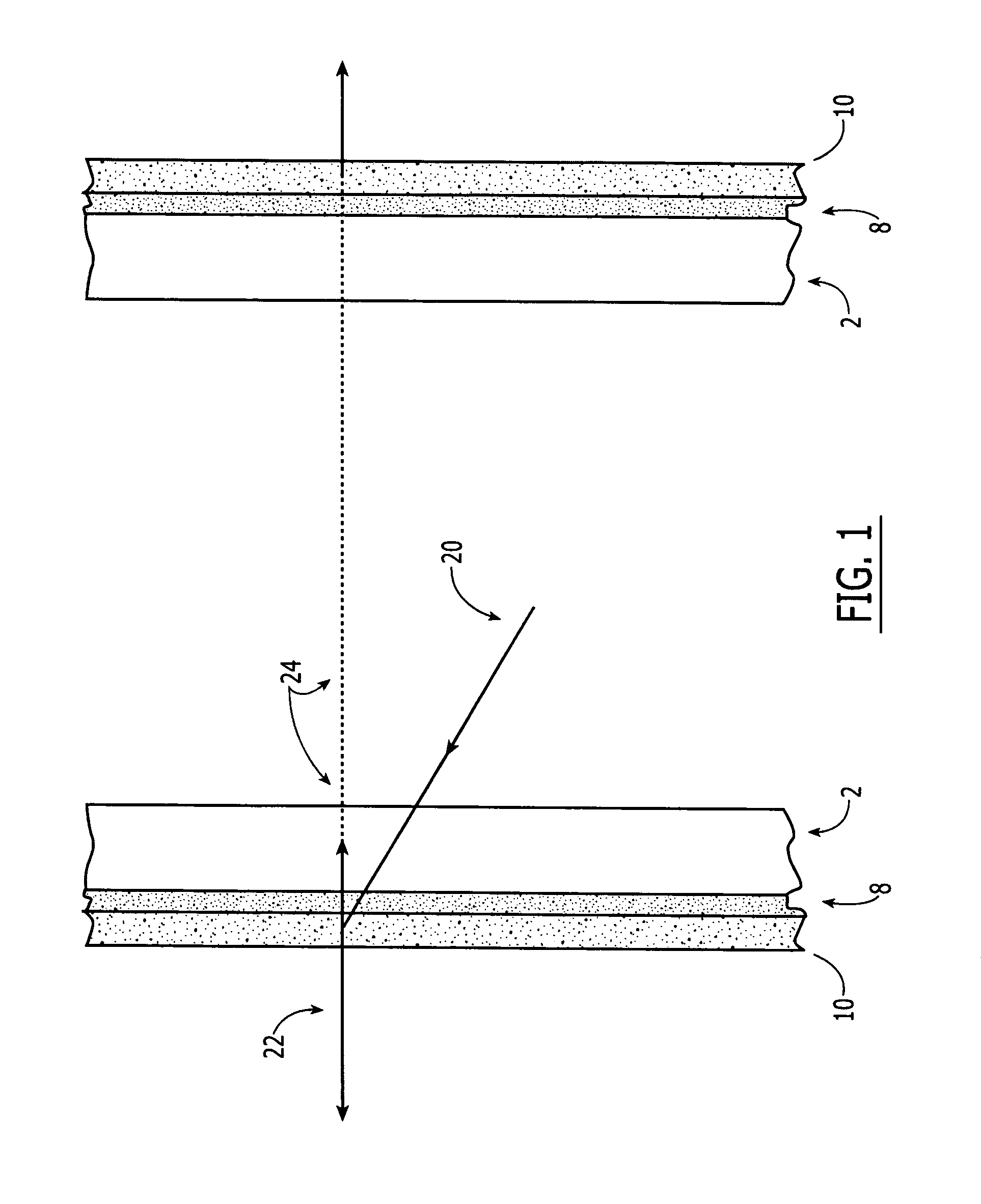
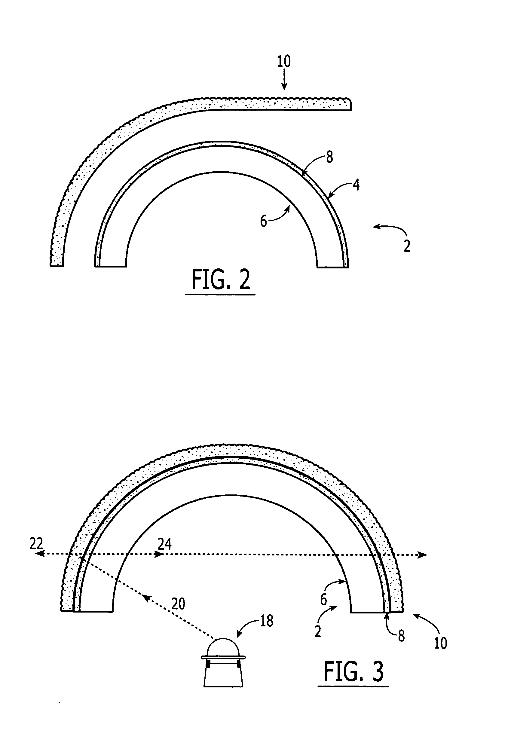
[0017]FIG. 1 illustrates the general principle upon which the tinted attenuation layer will enhance the contrast of the rear projection screen in a completely-darkened room. The figure is sectional view of a three-dimensional rear projection screen showing a tinted attenuation layer 8 disposed between a transparent substrate 2 and a diffusion layer 10. Because the screen has a three-dimensional form such as a sphere, cylinder, or cube, the figure shows opposing sides of the screen in which the transparent substrate 2 faces the source of the projected light and the diffusion layer faces the audience. The projected beam of light 20 is transmitted to the screen with an intensity represented by IS and is attenuated by the tinted attenuated layer 8 by a transmission factor represented by TT. The fraction of light that is forward scattered by the diffusion layer 10 is represented by f and the fraction of light that is back scattered is represented by (1−f). The tinted filter layer 8 will ...


PUM


Abstract

A three-dimensional rear projection screen that has substantially improved contrast by using a tinted layer disposed between the source of the projected light and the light diffusion layer. This tinted attenuation layer diminishes the back-scattered light more than it diminishes the desired forward-scattered light which makes up the image on the screen. The contrast of the image is thus improved because the reduction of the back-scattered light relative to the forward-scattered light diminishes the degradation of contrast caused by the impingement of spurious light onto opposite portions of the rear projection screen.

Description

CROSS-REFERENCED TO RELATED APPLICATIONS[0001]NoneFEDERALLY SPONSORED RESEARCH[0002]NoSEQUENCE LISTING OR PROGRAM[0003]Not ApplicableBACKGROUND OF THE INVENTION[0004]Rear projection is an arrangement in which the viewer sees an image on a screen, the image of which is provided by projecting light from behind the screen through means such as a source projector located behind the screen. The light from the source projector is thus directed toward the audience, and the screen material serves to scatter the light so that it appears to come from all points on the screen and not directly from the projector. When projecting onto a three-dimensional wrap-around screen, the image is formed on the surface of a translucent diffusion layer which may be bonded to a rigid transparent substrate. Rear projection screens are available in rigid and nonrigid configurations. Suitable materials for the substrate material used in rigid screens include acrylic, polyethylene terephthalate, and polycarbonat...

Claims


Application Information

Patent Timeline
IPC IPC(8): G03B21/56
CPCG03B21/56G03B21/62
Inventor LIGON, THOMAS R.
Owner LIGON THOMAS R
Why Eureka
Try Eureka