Electromagnetic apparatus and method for nerve localization during spinal surgery

a nerve localization and electric device technology, applied in the field of nerve localization during spinal surgery, neurosurgery and orthopedics, can solve the problems of spinal nerve damage accompanied by chronic pain in the patient, nerve root damage or pressure on the spinal cord, and difficulty in achieving

Inactive Publication Date: 2011-11-08
WOLF II ERICH
View PDF7 Cites 158 Cited by
  • Summary
  • Abstract
  • Description
  • Claims
  • Application Information

AI Technical Summary

Benefits of technology

[0038]Another preferred embodiment includes providing an electromagnetic awl with multiple cores and / or specially wound coils and / or Faraday shields to directionally orient the electromagnetic field with respect to the axis of the electromagnetic awl. In a still further embodiment, an electronic controller sweeps the intensity and position of the electromagnetic field with respect to the axis of the electromagnetic awl while simultaneously displaying the position of the sweep in order to aid in location of the pedicle wall and / or other sensitive nerve tissues.

Problems solved by technology

If not placed properly, the pedicle screws 23 (or pedicle screws 21) may breach the vertebral walls thereby leading to nerve root damage or pressure on the spinal cord.
The position and angle of the pilot hole is crucial to a successful pedicle screw placement and can be difficult to achieve, especially in percutaneous operations.
If the pilot hole breaches the pedicle wall, spinal nerve damage may occur accompanied by chronic pain in the patient.
Worse yet, if the pedicle wall is breached medially in the cervical or thoracic spine, permanent spinal cord damage may result.
Also, a breach will typically weaken the mechanical integrity of the pedicle screw fixture.
In the prior art, the ability to accurately judge the integrity of the pedicle is generally limited to post-operative observation.
Corrective surgery to reposition the malpositioned pedicle screw is expensive, carries inherent medical risks, and may not reverse the neurological deficit or pain.
But placement errors still occur.
While flouroscopic-assisted pedicle screw guidance decreases the risk of misplacement such equipment is expensive and is not universally available.
Hence the methods developed in the prior art have not been entirely successful.
One shortcoming of the prior art electrostatic pedicle awl is that the electric field generated is not well contained.
The lack of containment of the electric field often results in false readings.
Inaccurate EMG signals often lead to false placement failure and unnecessary alternative fixation procedures.
Unnecessary procedures cause higher patient morbidity and potential liability.
These similar problems exist in other prior art surgical procedures in which avoidance of nerves is critical, including the extreme lateral interbody fusion procedure (“XLIF procedure”).

Method used


Image

  • Electromagnetic apparatus and method for nerve localization during spinal surgery
  • Electromagnetic apparatus and method for nerve localization during spinal surgery
  • Electromagnetic apparatus and method for nerve localization during spinal surgery

Examples


Embodiment Construction

[0070]The numerous innovative teachings of the present invention will be described with particular reference to the presently preferred embodiments (by way of example, and not by way of limitation).

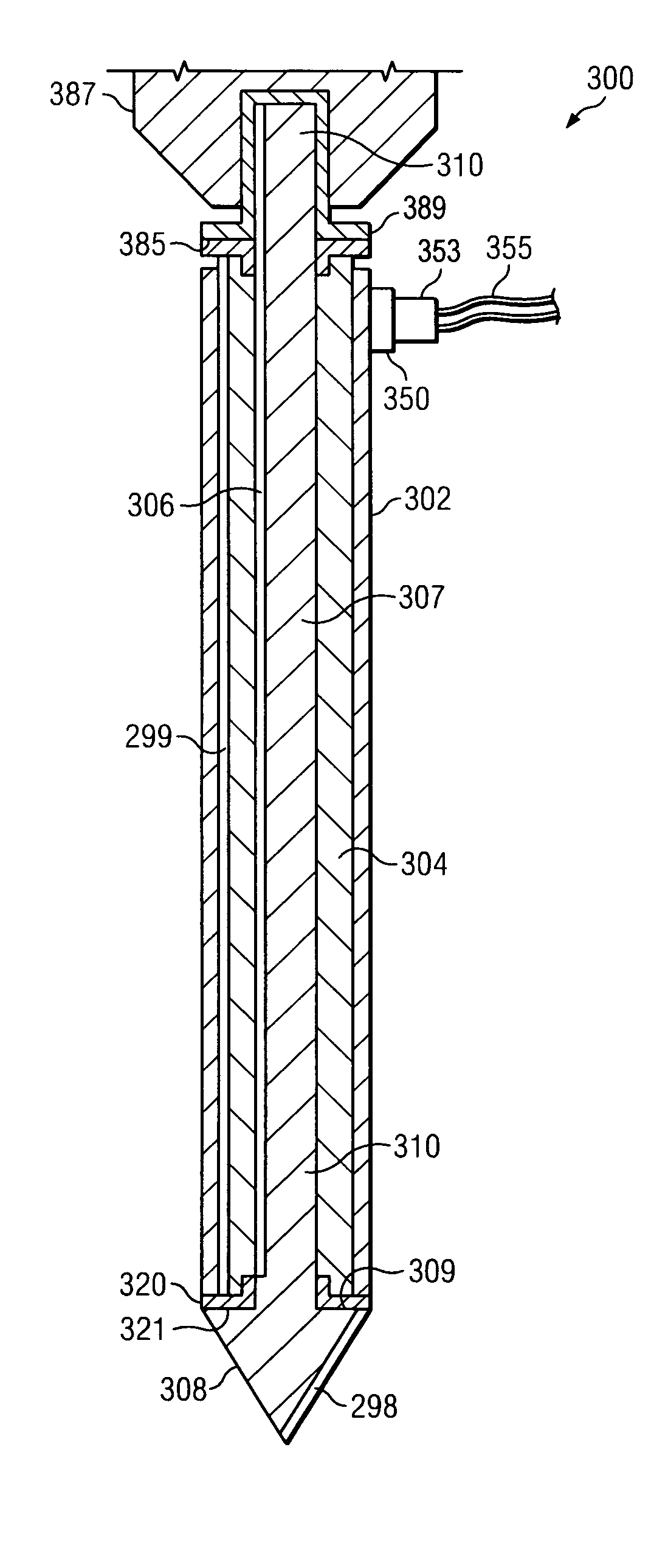
[0071]An electromagnetic pedicle awl is disclosed that utilizes a tightly focused time-varying magnetic flux to create a localized electromotive force (EMF) near the tip of electromagnetic pedicle awl 200 as shown in FIG. 5 and following. The localized EMF creates corresponding localized eddy currents which excite nearby nerves. The excitation is detected by an electromyographic recording device. In comparison to electrostatic pedicle awl 100 of the prior art, electromagnetic pedicle awl 200 excites nerves in close proximity to the tip as opposed to the more general excitation provided by the prior art. Electromagnetic pedicle awl 200 in combination with EMG detector 240 creates a system that is highly sensitive to the pedicle hole position.

[0072]According to Faraday's law of induction fo...


PUM


Abstract

An electromagnetic pedicle awl utilizes a tightly focused time-varying magnetic flux to create a localized electromotive force (EMF) near the tip of a pedicle awl. The localized EMF creates localized eddy currents in nearby nerves which in turn excite ionic nerve channels, the excitation being detected by an electromyographic recording device. In comparison to the electrically stimulated pedicle awl of the prior art, the electromagnetic pedicle awl only excites nerves directly in front of and directly to the side of the tip. The electromagnetic pedicle awl is comprised of a tapered awl or drill tip in combination with a solid core surrounded by a solenoid. A pulsed electric current source drives the solenoid to create a time-varying magnetic field in the vicinity of the tapered tip. The awl or drill tip may be stationary with respect to the solenoid or it may rotate. The electromagnetic pedicle awl in combination with an EMG detector connected to a patient is very sensitive to the pedicle hole position with respect to adjacent nerves and reduces false placement failure.

Description

CROSS-REFERENCE TO RELATED APPLICATION[0001]This application claims priority to U.S. Provisional Application Ser. No. 60 / 849,858 entitled “Electromagnetic Pedicle Screw Placement Apparatus and Method” which was filed on Oct. 6, 2006.COPYRIGHT NOTICE[0002]A portion of the disclosure of this patent document contains material which is subject to copyright protection. The copyright owner has no objection to the facsimile reproduction by anyone of the patent document or the patent disclosure as it appears in the Patent and Trademark Office patent file or records, but otherwise reserves all copyright rights whatsoever.FIELD OF INVENTION[0003]The present invention relates generally to the avoidance of nervous system injury during surgery for correction of spinal column injuries, degeneration and deformities in the fields of neurosurgery and orthopedics. More specifically, the invention is used for the placement of medical instrumentation apparatus into and between spinal vertebrae.BACKGROU...

Claims


Application Information

Patent Timeline
Patent Type & Authority Patents(United States)
IPC IPC(8): A61B17/16
CPCA61B5/0488A61B5/05A61B17/1671A61B5/4836A61B17/1703A61B2017/00039A61B2017/00154A61N1/0551A61B5/4041A61B5/389A61B5/395
Inventor WOLF, II, ERICH
Owner WOLF II ERICH
Why Eureka
Try Eureka